Split rolling basket

a basket and split technology, applied in the field of split rolling baskets, can solve the problems of most or all of the baskets encountering residue problems, etc., and achieve the effects of reducing or eliminating plugging in high residue conditions, reducing construction costs, and simplifying construction

Active Publication Date: 2010-10-05
DEERE & CO
View PDF19 Cites 26 Cited by
  • Summary
  • Abstract
  • Description
  • Claims
  • Application Information

AI Technical Summary

Benefits of technology

[0004]The present invention provides a single, center-mounted arm located directly above the row area of a strip-till berm. Basket halves are rotatably connected to the arm on opposite sides of the arm so the residue flow encounters rolling baskets rather than fixed arms so that catching, flipping and twisting of residue is minimized and plugging in high residue conditions is reduced or eliminated. A single arm and bearing mount arrangement simplifies construction and reduces cost compared to baskets with multiple arm supports. The single arm-supported baskets are self-cleaning, and the basket structure works more effectively in wet and heavy residue conditions than most previously available structures.

Problems solved by technology

Several types of rolling baskets are available, but most or all of such baskets encounter residue problems.
The two adjacent brackets catch, flip and twist residue, and this residue action causes plugs in high residue conditions such as encountered in corn stubble.

Method used


Image

  • Split rolling basket
  • Split rolling basket
  • Split rolling basket

Examples


Embodiment Construction

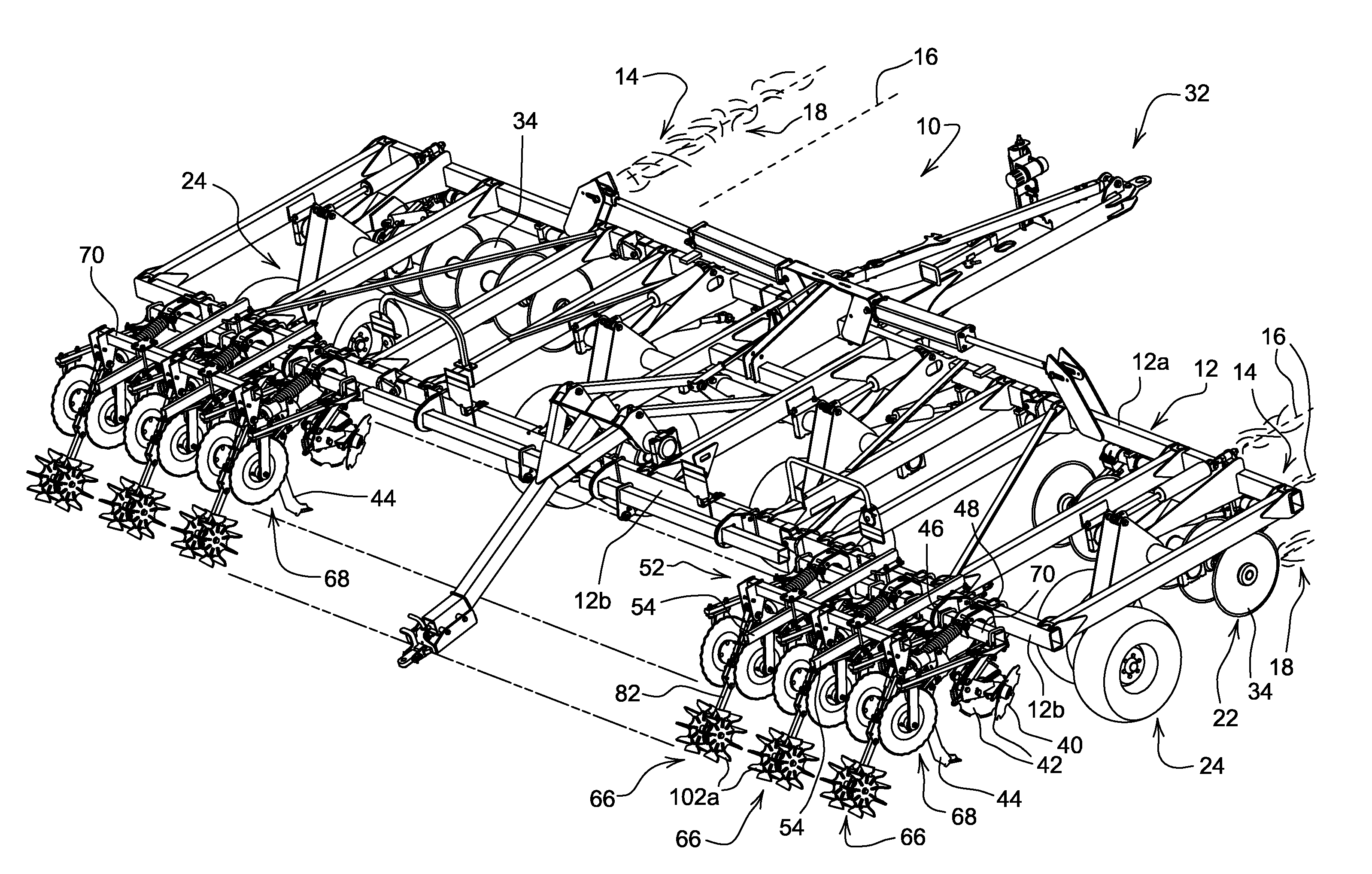
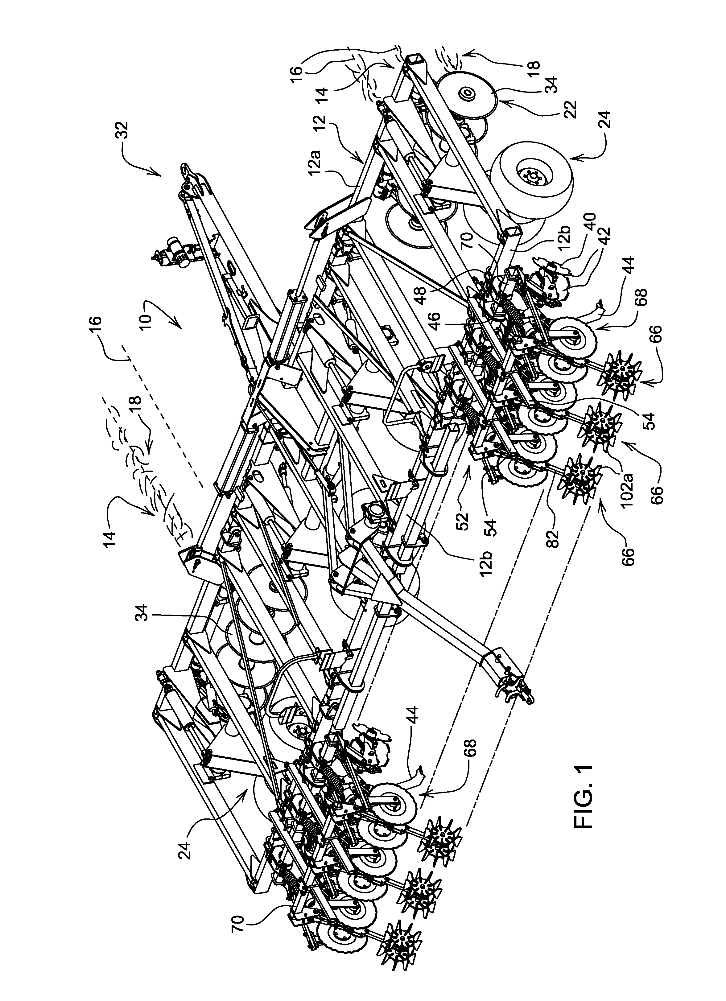
[0009]Referring now to FIG. 1 therein is shown a strip tillage implement 10 having a main frame 12 supported for forward movement over soil with residue 14 located generally in crop rows 16 on berms 18. Strip tillage tools 40 and 22 are supported from the frame 12 rearwardly and forwardly, respectively, of lift and depth control wheel assemblies 24. A forward hitch 32 is adapted for connection to a tractor (not shown).

[0010]The forward tools 22 include a coulter 34 supported from the forward beam 12a of the frame 12 at each crop row 16. The coulter provides a centrally located slit in the corresponding berm 18. The rearward strip tillage tools, shown as row cleaners 40, are supported from the rearward beam 12b with rearwardly diverging angled discs 42 for clearing residue from an area on opposite sides of the central slit. A shank 44 is supported from a spring trip shank assembly 46 connected by a bracket 48 to the rearward beam 12b. Each shank 44 is aligned with the corresponding c...


PUM


Abstract

A strip tillage implement includes a single, center-mounted arm located directly above the row area of a strip-till berm. Basket halves are rotatably connected to opposite sides of the arm in cantilever fashion to eliminate outer support arms. Residue flow encounters rolling baskets rather than fixed arms so that catching, flipping and twisting of residue is minimized and plugging in high residue conditions is reduced. A single, center-mounted bearing and simplified basket halves reduce the cost and complexity of the implement.

Description

FIELD OF THE INVENTION[0001]The present invention relates generally to strip tillage implements and, more specifically, to rolling basket structure for such implements.BACKGROUND OF THE INVENTION[0002]Numerous growers are changing from no-till or minimum tillage methods to strip tillage methods to reduce production costs and increase crop yields. Strip tillage machines typically work the soil in a zone and apply fertilizer. The strip tillage operation is completed in the fall, winter and spring seasons in the United States in varying conditions. When the strip tillage implement is used in the spring just prior to planting of the crop, a rolling basket may be attached behind a coulter, row cleaner, shank and closing disc to form a berm that is conducive to the planting and uniform germination of seeds.[0003]Currently available rolling baskets are typically constructed from flat metal bars which chop up dirt clods as they roll over the berm. Some baskets have a concave cut-out to prov...

Claims


Application Information

Patent Timeline
Patent Type & Authority Patents(United States)
IPC IPC(8): A01B49/02
CPCA01B33/021A01B49/02
Inventor STEINLAGE, DAVID L.FRIEDLEY, VERNON EUGENE
Owner DEERE & CO
Why Eureka
Try Eureka