Power tool with dynamic vibration damping

a technology of dynamic vibration damping and power tools, which is applied in the direction of shock absorbers, portable power-driven tools, portable drilling machines, etc., can solve the problems of increasing requiring a larger installation space in power tools, and poor space utilization efficiency, so as to improve the vibration reducing performance reduce the size of dynamic vibration reducers

Active Publication Date: 2010-10-05
MAKITA CORP
View PDF61 Cites 25 Cited by
  • Summary
  • Abstract
  • Description
  • Claims
  • Application Information

AI Technical Summary

Benefits of technology

[0007]Accordingly, it is an object of the invention to provide a technique that contributes to improvement of the vibration reducing performance of a dynamic vibration reducer in a power tool while reducing the size of the dynamic vibration reducer.
[0008]The above-described problem can be solved by a claimed invention. The representative power tool linearly drives a tool bit to perform a predetermined operation on a workpiece. The power tool includes a tool body and a dynamic vibration reducer. The power tool according to the invention may include power tools, such as a hammer, a hammer drill, a jig saw and a reciprocating saw, which perform an operation on a workpiece by linear movement of a tool bit. The dynamic vibration reducer includes a weight that linear moves in an axial direction of the tool bit. The weight is provided on the tool body directly or via a body side member. Further, the dynamic vibration reducer includes an elastic element that elastically supports the weight on the tool body directly or via the tool body side member. The dynamic vibration reducer serves to reduce vibration of the tool body during hammering operation by the linear movement of the weight in the axial direction of the tool bit. Further, the weight has an internal space that extends in the axial direction of the tool bit from at least one end of the weight in the axial direction. One end of the elastic element in the axial direction of the tool bit is inserted and received in the internal space, while the other end is placed on the tool body or the body side member.
[0009]According to this invention, with the construction in which the internal space is formed in the weight and extends in the axial direction of the tool bit and the elastic element is inserted and received in the internal space, the weight can be disposed on the outer peripheral side of the elastic element. As a result, compared with a construction in which an elastic element is disposed on the outer peripheral side of the weight, the mass of the weight can be increased. Thus, the vibration reducing performance of the dynamic vibration reducer can be enhanced. Further, with the construction in which the elastic element is disposed in the internal space of the weight, if the elastic element comprises a coil spring, the diameter of the coil spring can be reduced. By reducing the diameter of the coil spring, a smaller stress is generated, so that the coil spring can be provided with a greater spring force while maintaining its durability. As a result, the vibration reducing performance of the dynamic vibration reducer can be further enhanced.

Problems solved by technology

Thus, in terms of ensuring the mass of the weight, it has a poor space utilization efficiency.
If the weight is increased in mass with the aim of improving the vibration reducing performance, the dynamic vibration reducer will be increased in size and thus require a larger installation space in the power tool.

Method used


Image

  • Power tool with dynamic vibration damping
  • Power tool with dynamic vibration damping
  • Power tool with dynamic vibration damping

Examples


first embodiment

of the Invention

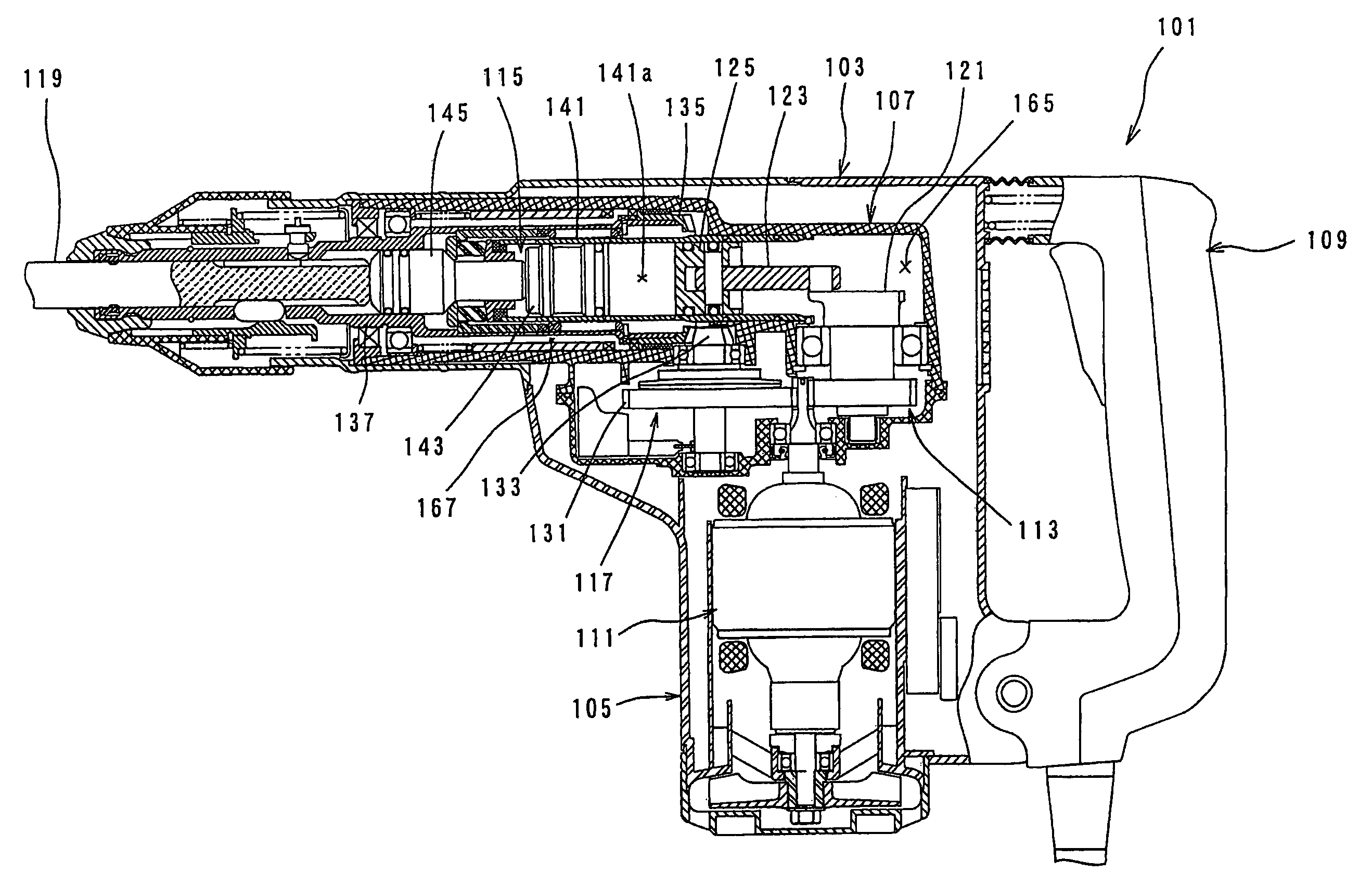
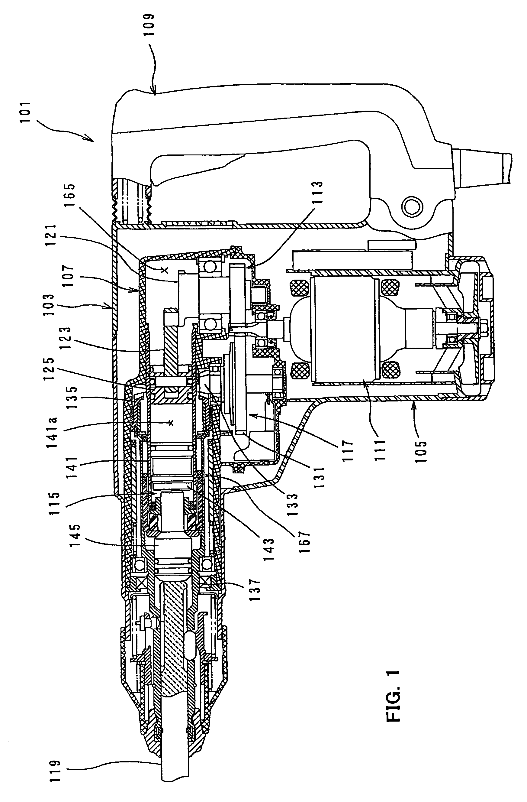
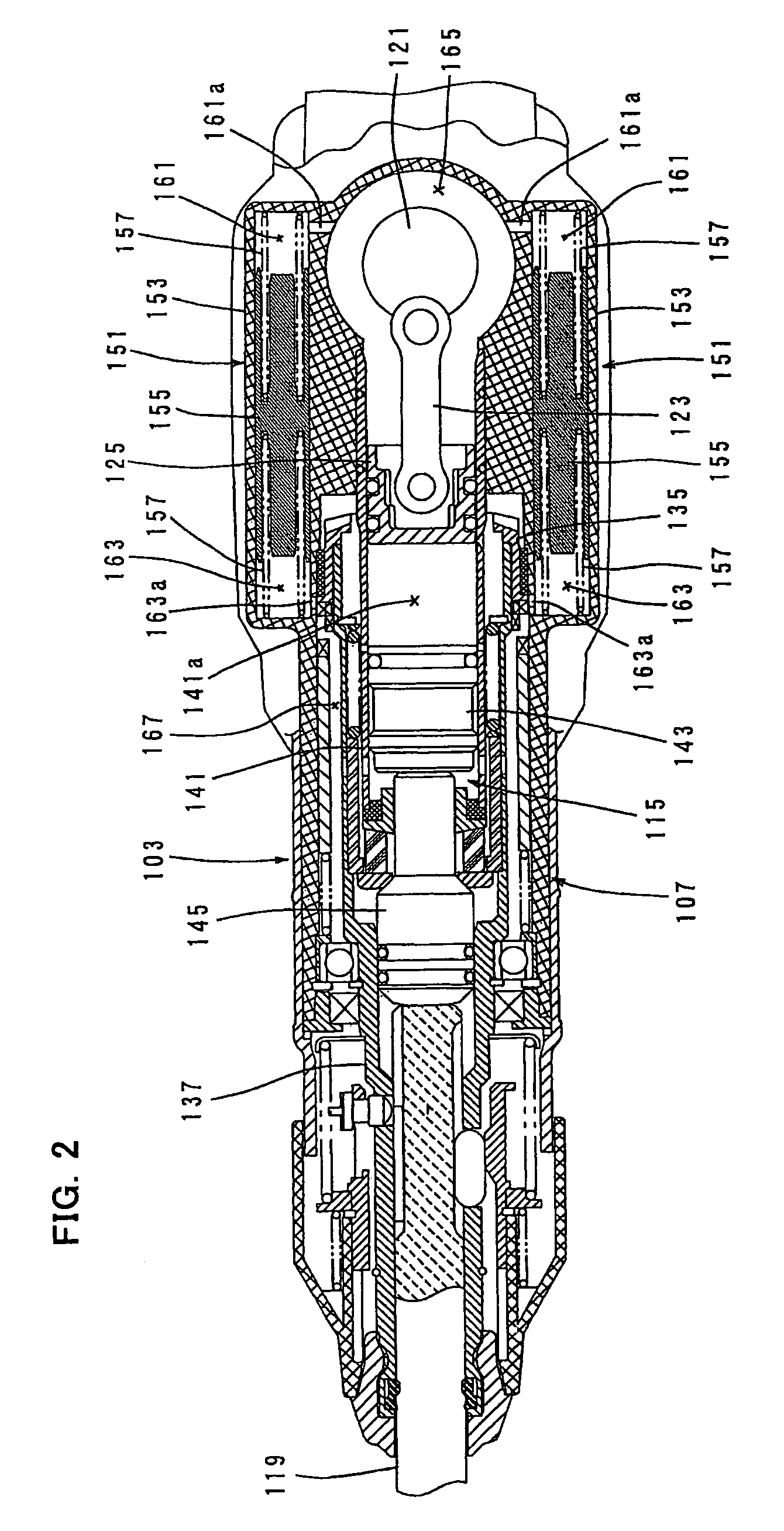
[0035]A first embodiment of the present invention is now described with reference to FIGS. 1 to 3. FIG. 1 is a sectional side view showing an entire electric hammer drill 101 as a representative embodiment of the power tool according to the present invention. FIG. 2 is a sectional plan view showing an essential part of the hammer drill. FIG. 3 is a sectional view of a dynamic vibration reducer.

[0036]As shown in FIG. 1, the electric hammer drill 101 of this embodiment includes a body 103 that forms an outer shell of the hammer drill 101, a tool holder 137 connected to the tip end region (on the left side as viewed in FIG. 1) of the body 103 in its longitudinal direction, a hammer bit 119 detachably coupled to the tool holder 137, and a handgrip 109 that is connected to the other end (on the right side as viewed in FIG. 1) of the body 103 and designed to be held by a user. The body 103 and the hammer bit 119 are features that correspond to the “tool body” and the “tool...

second embodiment

of the Invention

[0051]A second embodiment of the present invention is now described with reference to FIG. 4. The second embodiment is a modification to the construction of the weight 155 in the dynamic vibration reducer 151 and has the same construction as the above-described first embodiment except for the construction of the dynamic vibration reducer 151.

[0052]As shown in FIG. 4, the weight 155 of the dynamic vibration reducer 151 according to this embodiment has an outer cylindrical weight member 155A and an inner columnar weight member 155B which is formed separately from the cylindrical weight member 155A and housed within the cylindrical weight member 155A. The cylindrical weight member 155A and the columnar weight member 155B are features that correspond to the “second part” and the “first part”, respectively, according to this invention.

[0053]The cylindrical weight member 155A and the columnar weight member 155B have substantially the same axial length. The columnar weight ...

third embodiment

of the Invention

[0057]A third embodiment of the present invention is now described with reference to FIG. 5. The third embodiment is a modification to the above-described second embodiment. In this embodiment, in the dynamic vibration reducer 151, the cylindrical weight member 155A and the columnar weight member 155B housed within the cylindrical weight member 155A form the weight 155 and are integrally connected to each other by utilizing the biasing forces of the front and rear coil springs 157 which act on the cylindrical weight member 155A and the columnar weight member 155B toward each other. The cylindrical weight member 155A and the columnar weight member 155B are features that correspond to the “second part” and the “first part”, respectively, according to this invention.

[0058]In this embodiment, a positioning stopper in the form of a flange 155Aa is formed on the inner surface of the cylindrical weight member 155A generally in the middle in the axial direction and protrudes...


PUM

PropertyMeasurementUnit
weightaaaaaaaaaa
rotationaaaaaaaaaa
diameteraaaaaaaaaa

Abstract

It is an object of the invention to provide a technique that contributes to improvement of the vibration reducing performance of a dynamic vibration reducer in a power tool while realizing reduction in size of the dynamic vibration reducer. A representative power tool which linearly drives a tool bit to perform a predetermined operation on a workpiece includes a tool body and a dynamic vibration reducer. The dynamic vibration reducer has a weight and an elastic element. The weight has an internal space that extends in the axial direction of the tool bit from at least one end of the weight in said axial direction. One end of the elastic element is inserted and received in the internal space, while the other end of the elastic element is placed on the tool body directly or via the body side member.

Description

BACKGROUND OF THE INVENTION[0001]1. Field of the Invention[0002]The present invention relates to a vibration reducing technique of a power tool, such as a hammer and a hammer drill, which linearly drives a tool bit.[0003]2. Description of the Related Art[0004]Japanese non-examined laid-open Patent Publication No. 2004-154903 discloses an electric hammer having a vibration reducing mechanism. This known electric hammer has a dynamic vibration reducer as a means for reducing vibration caused in the axial direction of the hammer bit during hammering operation. The dynamic vibration reducer has a weight that can linearly move under a biasing force of an elastic element, and the dynamic vibration reducer reduces vibration of the hammer during hammering operation by the movement of the weight in the axial direction of the tool bit.[0005]In the known dynamic vibration reducer, the weight has a long columnar shape having a large-diameter portion and a small-diameter portion which are integr...

Claims


Application Information

Patent Timeline
Patent Type & Authority Patents(United States)
IPC IPC(8): B25D17/24
CPCB23D51/16B25D17/24F16F7/116B25F5/006B25D2211/003B25D2217/0092B25D2217/0084
Inventor AOKI, YONOSUKE
Owner MAKITA CORP
Why Eureka
Try Eureka