In-wall heater

a heater and wall technology, applied in the field of wall heaters, can solve the problems of room air not flowing easily into the space above the combustion housing, overheating of the room wall, etc., and achieve the effects of reducing the combustion range of the burner, removing and cleaning the filter, and reducing the combustion rang

Inactive Publication Date: 2010-10-05
RINNAI CORP +1
View PDF32 Cites 10 Cited by
  • Summary
  • Abstract
  • Description
  • Claims
  • Application Information

AI Technical Summary

Benefits of technology

[0011]With the above-described construction, the section where the air intake opening is provided is exposed to the front of the room wall, and therefore, the filter can be easily attached and detached to and from the air intake opening and maintainability is not impaired. Because the air intake opening is provided in the side plate portion of the outer case, a suction sound is radiated to the side of the heater and the noise level of a suction sound in front of the heater decreases.
[0025]Incidentally, it is preferred that in the place where the air intake opening of each side plate of the outer case is provided, a filter which covers the air intake opening is detachably mounted and that a louver member which covers the filter is attached so as to be able to open and close. With this construction, by closing the louver member on a steady basis, the filter is hidden from the sight and the appearance can be kept in good condition and by opening the louver member, it is possible to remove and clean the filter. Thus, maintainability is also improved.

Problems solved by technology

With this method, however, the room air does not flow easily into the space above the combustion housing within the outer case where the temperature is apt to rise, and there is a possibility that the overheating of the room wall may occur due to a rise in the temperature of the top surface of the outer case.

Method used


Image

  • In-wall heater
  • In-wall heater
  • In-wall heater

Examples


Embodiment Construction

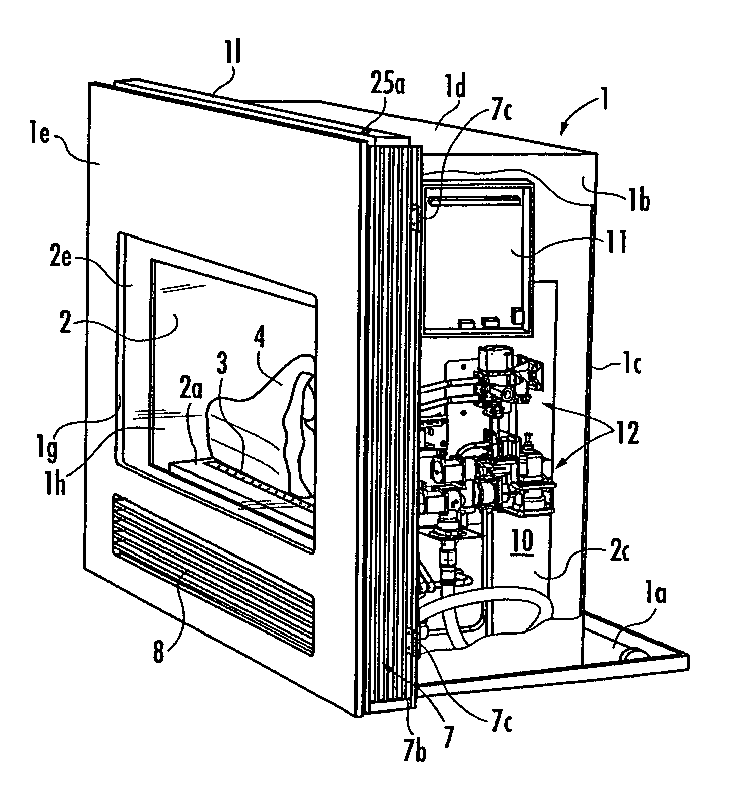
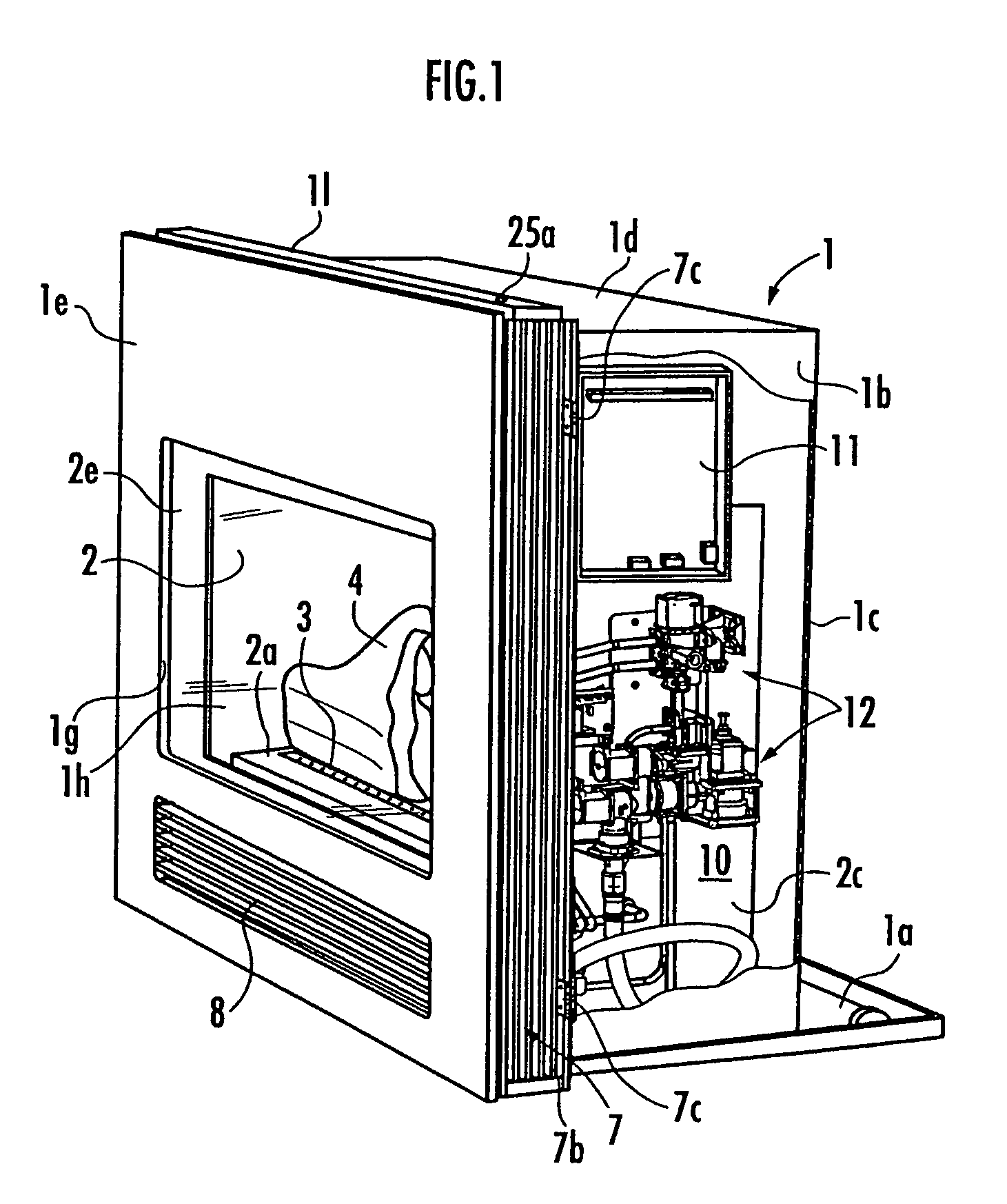
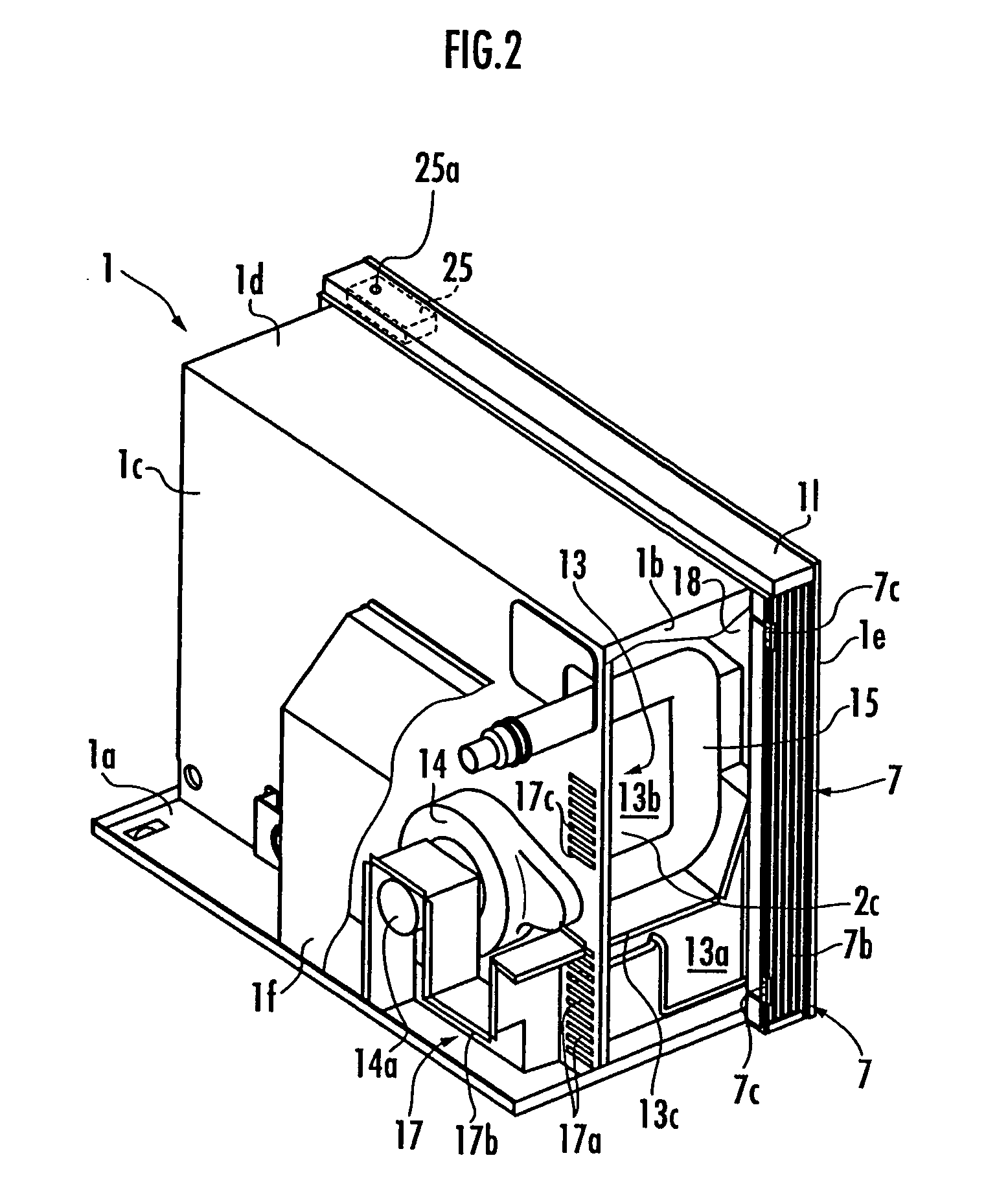
[0038]Hereinafter, an embodiment in which the present invention is applied to an in-wall fireplace-type heater will be described. As shown in FIGS. 1 to 4, this heater comprises an outer case 1 and a combustion housing 2 provided within the outer case 1. The outer case 1 is constituted by a bottom plate portion 1a, right and left side plate portions 1b, a back plate portion 1c, a top plate portion 1d, a front panel 1e, and an extension case if which is attached to a left-side part of the back surface of the back plate portion 1c. As shown in FIG. 4, the outer case 1 is installed by being embedded in a recess Wa which is formed in a room wall W, and only the front part of the outer case 1 is exposed to the front side of the room wall W.

[0039]A burner 3 is disposed in the lower part within the combustion housing 2. A burner supporting plate 2a having an opening into which a top end portion of the burner 3 is to be fitted is disposed within the combustion housing 2, and an artificial f...


PUM


Abstract

In an in-wall heater, in which control equipment 11, 12 is disposed in a side space 10 on one lateral side of a combustion housing 2 within an outer case 1 and an exhaust duct 15 is disposed in a side space 13 on the other lateral side of the combustion housing 2, the cooling performance of each of the side spaces is increased and noise due to a sucked-in sound of room air can be reduced. In a side plate portion of the outer case 1 on both lateral sides, an air intake opening 7, which is vertically long, is provided in a position in a front side portion exposed to a front of a room wall. Each side space 10, 13 within the outer case 1 is formed in a ventilation flue on the suction side where the room air from each of the air intake openings 7 is conducted into the warm air fan 9.

Description

BACKGROUND OF THE INVENTION[0001]1. Field of the Invention[0002]The present invention relates to an in-wall heater which is disposed by being embedded in a recess formed in a room wall.[0003]2. Description of the Related Art[0004]As an in-wall heater of this kind, there has hitherto been known an in-wall heater which comprises an outer case, a combustion housing which is provided within the outer case and in which a burner is built, a heat exchanger which is provided within the outer case so as to be positioned behind the combustion housing and causes combustion exhaust gas from the combustion housing to flow, an air intake opening and a blast opening each provided in the outer case, a warm air fan within the outer case which sucks in room air from the air intake opening and sends the air into the room from the blast opening via a section where the heat exchanger is disposed, control equipment which is disposed in a side space on one lateral side between the outer case and the combu...

Claims


Application Information

Patent Timeline
Patent Type & Authority Patents(United States)
IPC IPC(8): F24C15/06F24C3/04F24C3/00F24C15/22F23J11/00
CPCF24B1/1808
Inventor TSUNEKAWA, IKUOOGURI, MINORUKANEIWA, SATOSHISMITH, BRIANBRINSDEN, GREGORY
Owner RINNAI CORP
Why Eureka
Try Eureka