Methods and apparatus for providing a semiconductor optical flexured mass accelerometer

a technology of optical flexured mass and accelerometer, which is applied in the direction of distance measurement, devices using optical means, instruments, etc., can solve the problems of difficult positioning and alignment, subject to misalignment, and difficult to provide precise acceleration measurements, so as to increase the accuracy of acceleration computation

Inactive Publication Date: 2010-10-05
CHARLES STARK DRAPER LABORATORY
View PDF13 Cites 19 Cited by
  • Summary
  • Abstract
  • Description
  • Claims
  • Application Information

AI Technical Summary

Benefits of technology

[0008]In some embodiments of the invention, an acceleration measurement assembly is constructed by monolithic integration using standard semiconductor batch processing techniques. This allows for mass production of optical circuits and a reduction in size and cost. Accordingly, multiple measurement assemblies which are not achievable in conventional systems can be combined to provide accurate acceleration measurements.
[0010]Polarizers and PBS are not required to direct the light beam through the semiconductor substrate towards the flexured mirror. Accordingly, a single polarization state can be maintained throughout the acceleration measurement process.
[0012]In some embodiments, split and detect circuitry may include diagnostics and compensation circuitry for detecting various changes in the characteristics of the light beams before they leave the semiconductor substrate and after they are reflected by the external mirrors. These characteristics may be used to increase the accuracy of the acceleration computation by allowing for the compensation of, for example, hardware thermal expansion and contraction and changes in light intensity.

Problems solved by technology

The discrete components required in the measurement assembly typically occupy a large amount of space making it difficult to provide precise measurements of acceleration.
Moreover, the discrete components are difficult to position and align to provide the desired behavior and are subject to be misaligned with changes in external conditions.
However, size limitations of the accelerometers restrict the ability to manufacture multiple measurement assemblies.
Removing errors caused by this signal requires calibration and additional computation and is inefficient.

Method used


Image

  • Methods and apparatus for providing a semiconductor optical flexured mass accelerometer
  • Methods and apparatus for providing a semiconductor optical flexured mass accelerometer
  • Methods and apparatus for providing a semiconductor optical flexured mass accelerometer

Examples


Embodiment Construction

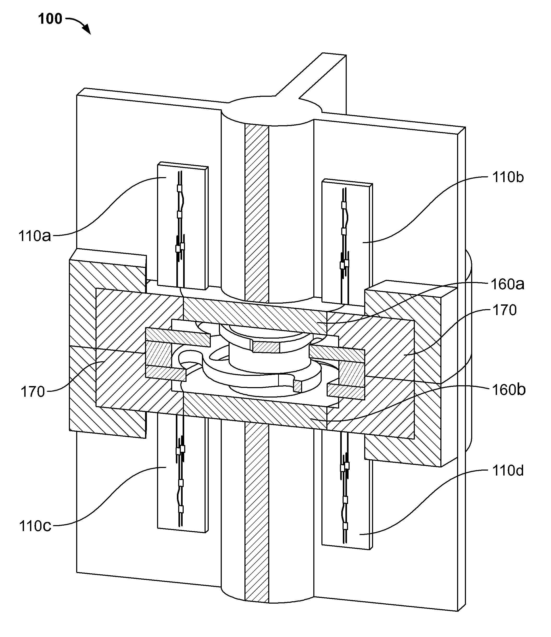
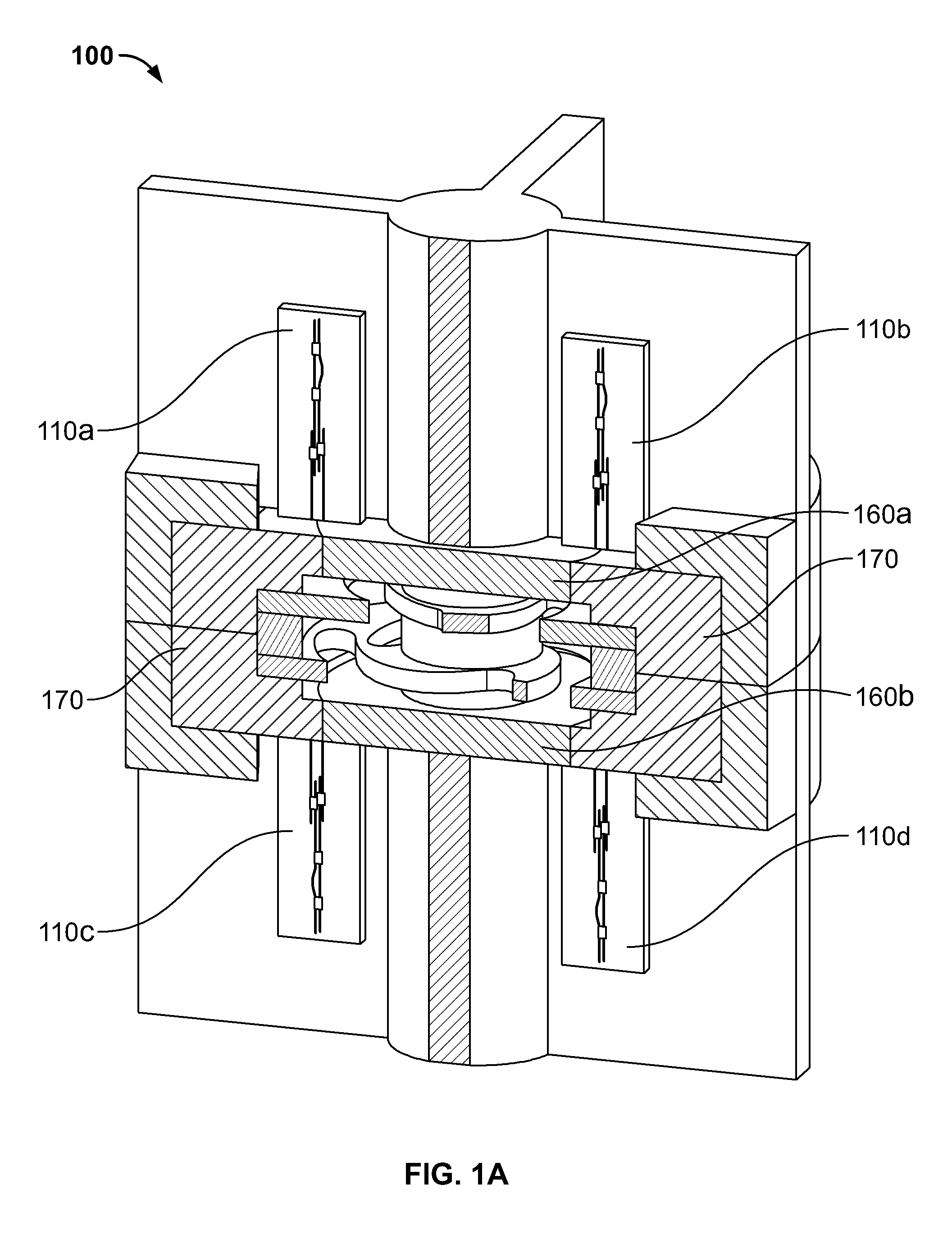
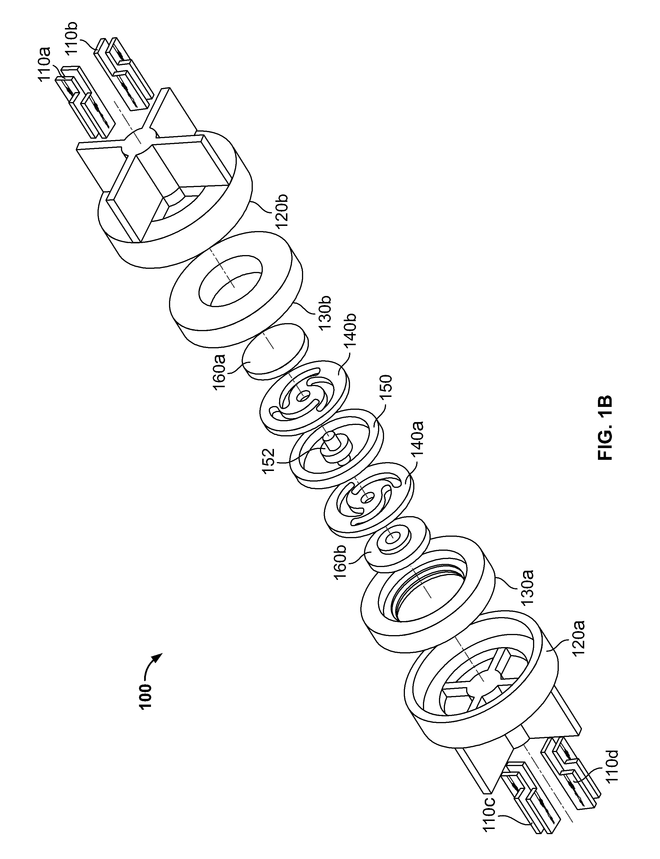
[0021]FIG. 1A is a three-dimensional diagram of illustrative components of an optical accelerometer 100 in accordance with an embodiment of the present invention. The accelerometer 100 includes semiconductor optical accelerometers 110a-d, flexure cartridge assemblies 160a-b, and a static assembly 170. As defined herein, the term “accelerometer” refers to any body or system that includes one or more acceleration measurement devices and the term “semiconductor optical accelerometer” refers to an integrated circuit device that is placed in or on the accelerometer for providing a measurement of acceleration based on optical properties of light generated and measured by the device.

[0022]In the accelerometer 100, multiple semiconductor optical accelerometers 110a-d can be incorporated onto a single accelerometer body or system because of the size reduction achieved over the conventional accelerometer measurement devices. Although only four such optical accelerometers are shown in accelero...


PUM


Abstract

Methods and apparatus are provided for integrating various optical components onto a planar substrate using a single semiconductor material system to produce an accelerometer. A light beam is generated on the semiconductor optical accelerometer. The light beam is split to form two light beams using a multimode interference (MMI) coupler. One of the two light beams that is formed is directed towards a reference mirror and the other is directed towards a flexured mirror. The flexured mirror moves as a result of acceleration and thereby reflects the light beam with a different light beam characteristic. The light beams are combined by the MMI coupler to produce an interference light beam. A microprocessor measures acceleration based on the differences in light beam characteristics of the reflected light beams. Along the optical path light beam detectors measure various beam characteristics. The microprocessor accounts for characteristics measured by the detectors when computing acceleration.

Description

FIELD OF THE INVENTION[0001]The present invention is directed to methods and apparatus for providing a semiconductor optical flexured mass accelerometer, and more particularly to integrating various optical components onto a planar substrate using a single semiconductor material system.BACKGROUND OF THE INVENTION[0002]Conventional optical accelerometers are manufactured from discrete components that are used to direct light in various directions in order to ultimately measure acceleration based on changes in the light. Each of these discrete components is manufactured separately and is placed at a different location on the accelerometer body. Typically, some of these components include polarizers, polarized beam splitters (“PBS”) and static mirrors that direct the light beam towards different detectors and moving parts (e.g., a proof mass mirror or flexured mirror).[0003]The conventional optical accelerometers measure acceleration using a Michelson interferometer assembly. Each of t...

Claims


Application Information

Patent Timeline
Patent Type & Authority Patents(United States)
IPC IPC(8): G01C3/08G01P3/36
CPCG01P15/093
Inventor TAWNEY, JESSEHAKIMI, FARHAD
Owner CHARLES STARK DRAPER LABORATORY
Why Eureka
Try Eureka