
Modular power distribution system having a sealing arrangement for use in a work machine

a technology of module power distribution system and work machine, which is applied in the direction of electrical apparatus casing/cabinet/drawer, substation/switching arrangement casing, coupling device connection, etc., can solve the problems of high inductance bus and difficult service of existing bus system

Inactive Publication Date: 2010-10-05
DEERE & CO
View PDF20 Cites 21 Cited by
  • Summary
  • Abstract
  • Description
  • Claims
  • Application Information

AI Technical Summary

Benefits of technology

The invention is a power distribution system for a work machine that includes a power electronics module, a module rack, and a power bus assembly. The power electronics module has power connectors that fit into the module rack, which has openings for sliding the module. The power bus assembly has power bus connectors that engage with the power connectors of the power electronics module. The system also includes gaskets that seal the power connectors and the power bus connectors to prevent leaks and ensure proper functionality. The technical effects of this system include improved power distribution and protection against electrical arcing, which can prolong the life of the work machine's electrical components.

Problems solved by technology

The bus is typically of high potential, e.g., 200 to 1000 volts (V), and may be subject to a number of possible problems when operated in a dirty or wet environment that may be experienced by a work machine, e.g., mobile agricultural machines, mobile construction machines, mobile transportation vehicles, etc.
Those problems may include, for example, bus to bus, bus to ground, phase to phase, and phase to ground short circuits.
Furthermore, some existing bus systems are difficult to service because of the orientation and quantity of connections.
In addition, many existing bus systems cause the power electronics to be largely isolated from each other resulting in a high inductance bus, which in turn requires each power electronics module to have large filtering capacitance.

Method used


Image

  • Modular power distribution system having a sealing arrangement for use in a work machine
  • Modular power distribution system having a sealing arrangement for use in a work machine
  • Modular power distribution system having a sealing arrangement for use in a work machine

Examples


Embodiment Construction

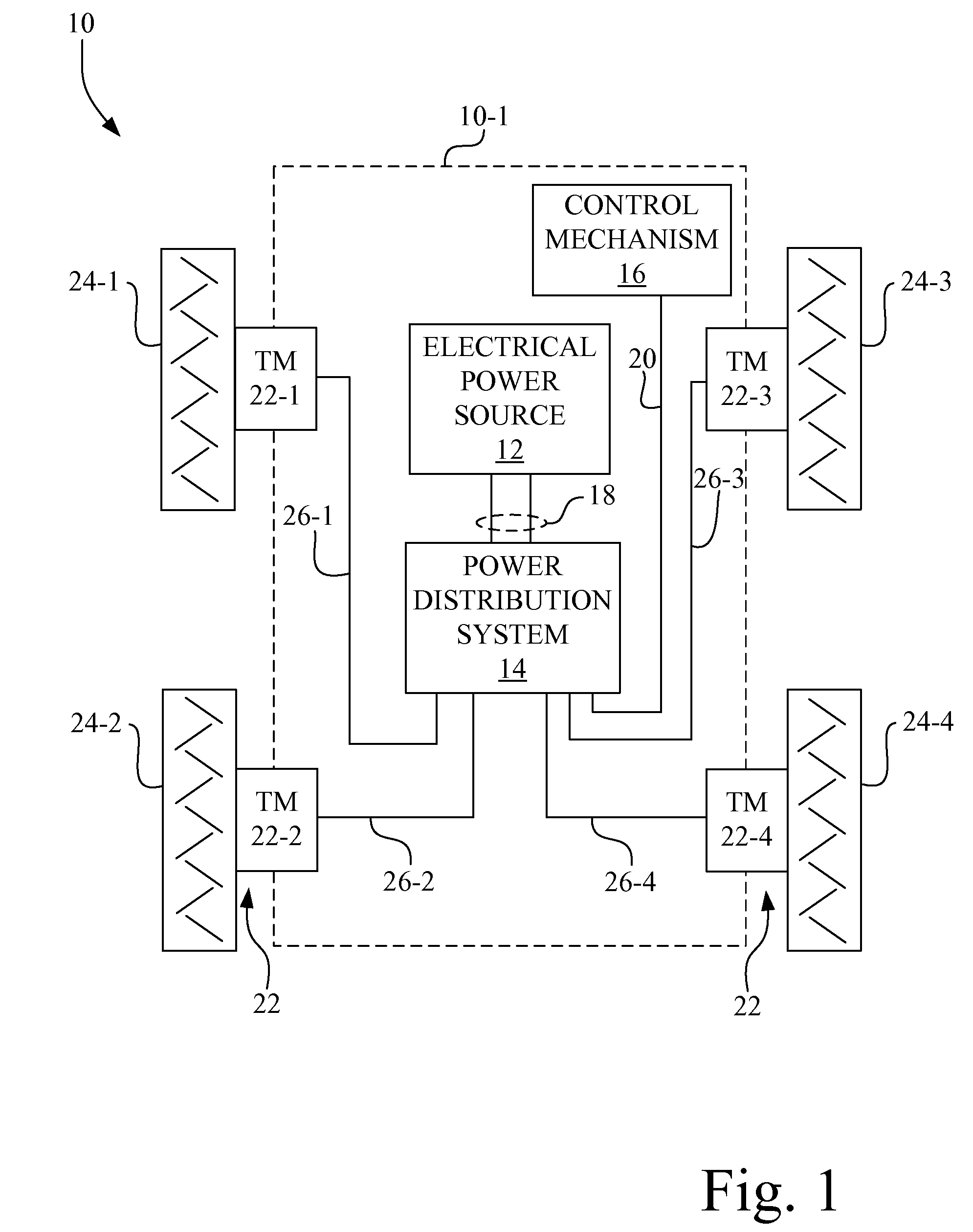
[0016]Referring now to the drawings, and more particularly to FIG. 1, there is shown a diagrammatic representation of a work machine 10 embodying the present invention.

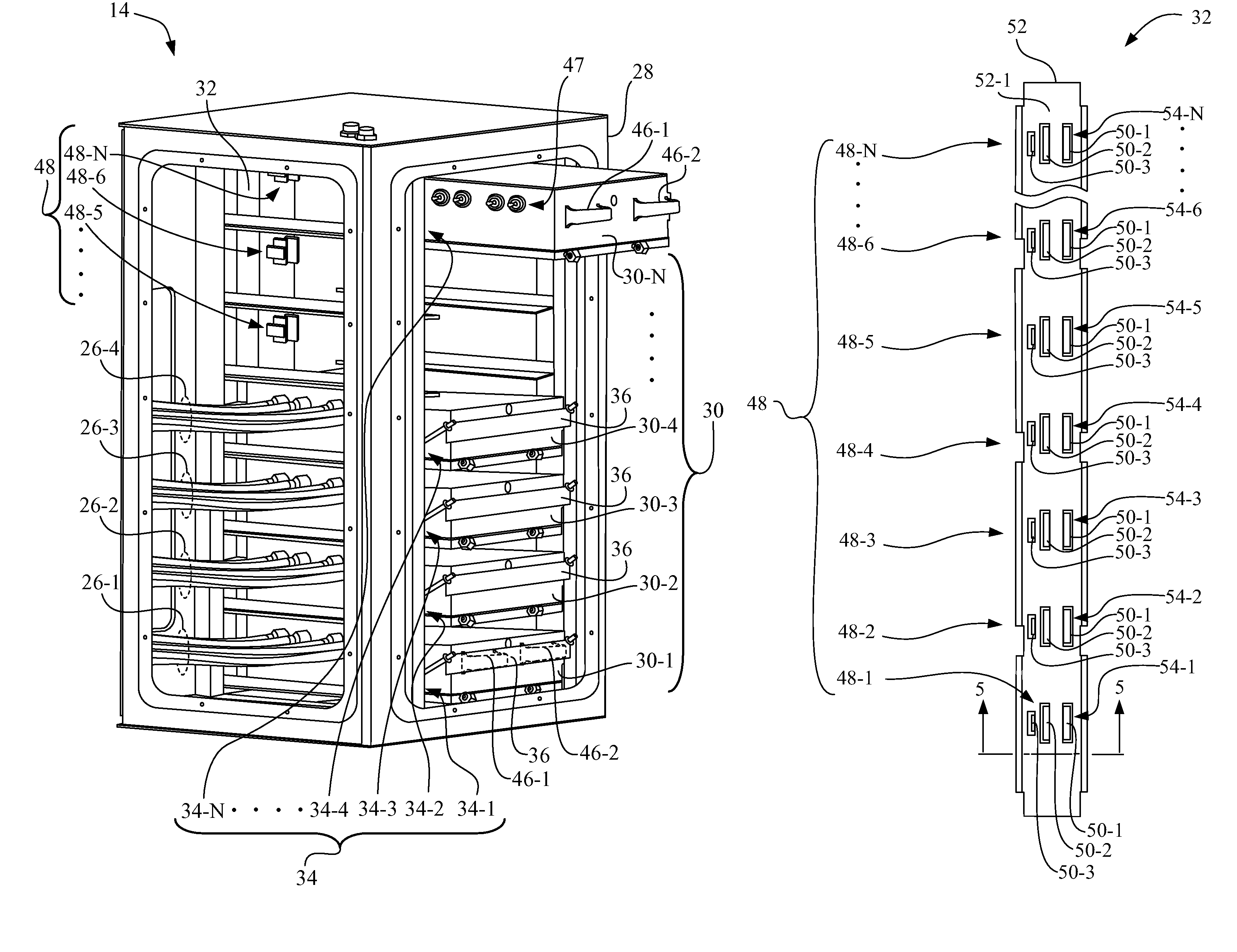
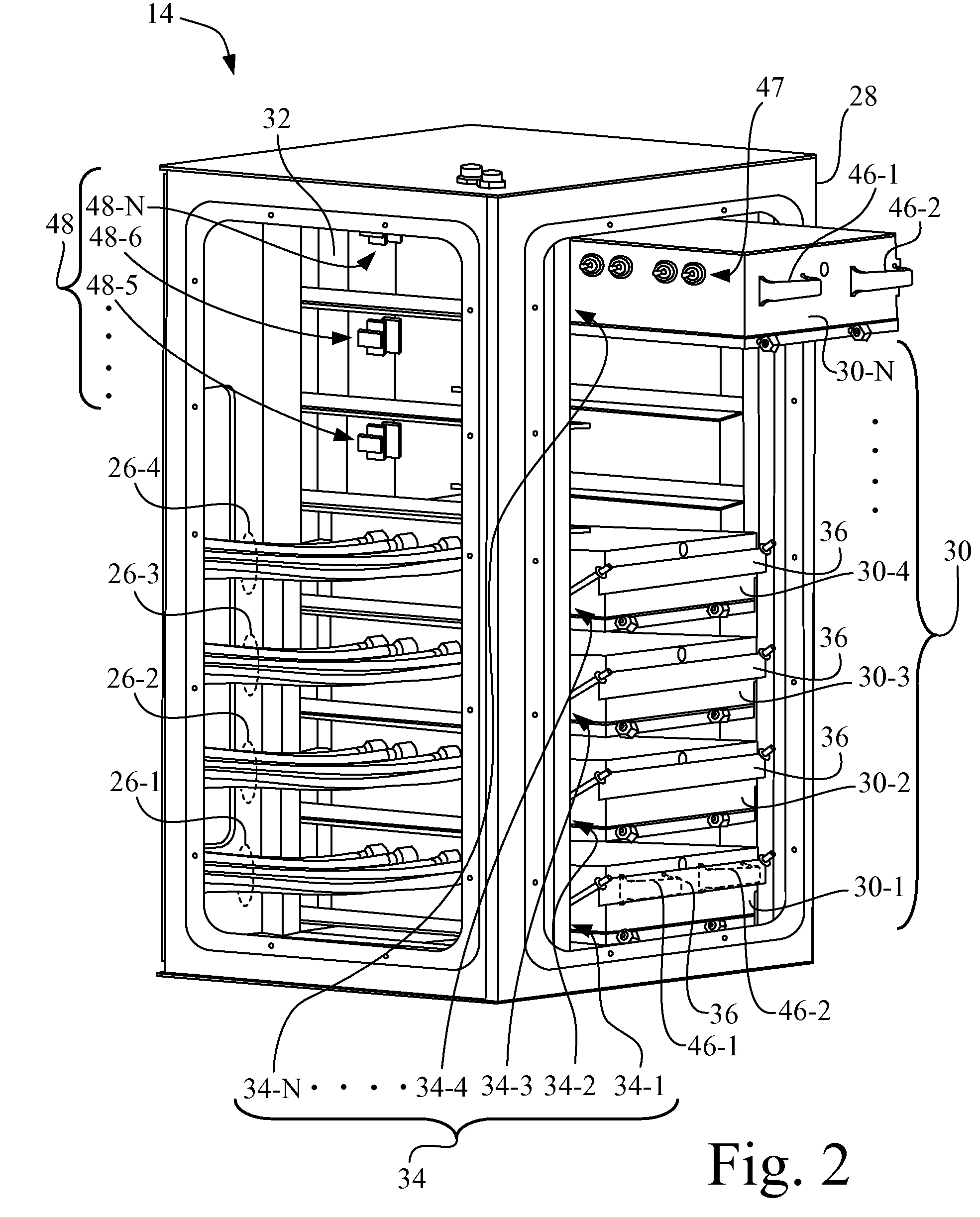
[0017]Work machine 10 includes a frame 10-1 to which an electrical power source 12, a power distribution system 14, and a control mechanism 16 are mechanically mounted. Electrical power source 12 is electrically connected to power distribution system 14 by a power cable 18, which may include multiple electrical cables, which in turn may include one or more electrical conductors. Control mechanism 16 may provide, for example, a plurality of electrical control output signals, such as a ground speed signal, steering output signals, braking output signals, etc., which are supplied to power distribution system 14 via a communication cable 20. A plurality of traction motors (TM) 22, individually identified by element numbers 22-1, 22-2, 22-3 and 22-4, is mounted to frame 10-1, and individually are connected to a correspondi...


PUM


Abstract

A power distribution system for a work machine includes a power electronics module having a set of power connectors to receive electrical power. A module rack has an opening for slidably receiving the power electronics module. A power bus assembly is mounted to the module rack. The power bus assembly has a set of power bus connectors located to be mechanically engaged by the set of power connectors of the power electronics module when the power electronics module is installed in the module rack. A gasket is interposed in a sealing arrangement between the power electronics module and the power bus assembly. The gasket is configured to extend completely around all power connectors of the set of power connectors and is configured to extend completely around each individual power connector of the set of power connectors.

Description

FIELD OF THE INVENTION[0001]The present invention relates generally to work machines, and more particularly, to a modular power distribution system having a sealing arrangement for use in a work machine.BACKGROUND OF THE INVENTION[0002]A typical electric drive propulsion system consists of a generator and corresponding power electronics which provide power on a voltage bus. The motor(s) and their corresponding power electronics take power off the bus to drive the traction motors. The bus is typically of high potential, e.g., 200 to 1000 volts (V), and may be subject to a number of possible problems when operated in a dirty or wet environment that may be experienced by a work machine, e.g., mobile agricultural machines, mobile construction machines, mobile transportation vehicles, etc. Those problems may include, for example, bus to bus, bus to ground, phase to phase, and phase to ground short circuits. Furthermore, some existing bus systems are difficult to service because of the or...

Claims


Application Information

Patent Timeline
Patent Type & Authority Patents(United States)
IPC IPC(8): H02B1/26
CPCH05K5/069H05K7/1411H05K7/1432H01R13/5219H05K7/14325
Inventor CHERNEY, MARK J.WIELAND, ANDREW D.
Owner DEERE & CO
Learn More