Dead zone activation in vapor-liquid contacting apparatus

a vapor-liquid contacting and dead zone technology, which is applied in the direction of combustion-air/fuel-air treatment, separation processes, carburetor air, etc., can solve the problems of reducing the capacity and mass transfer efficiency, and reducing the active area of the tray. , to achieve the effect of reducing the dead zone area, increasing the capacity of the vapor-liquid contacting tray, and improving the mass transfer efficiency of the vapor-liquid

Active Publication Date: 2010-10-12
UOP LLC
View PDF33 Cites 18 Cited by
  • Summary
  • Abstract
  • Description
  • Claims
  • Application Information

AI Technical Summary

Benefits of technology

[0013]An advantage of the present invention is that the capacity of a vapor-liquid contacting tray is increased. A further advantage of the present invention is that the mass transfer efficiency of a vapor-liquid contacting tray is improved. This is done by elevating the vapor-liquid contacting tray above the tray support, reducing the dead zone areas across the vapor-liquid contacting tray, and increasing the active area.
is that the capacity of a vapor-liquid contacting tray is increased. A further advantage of the present invention is that the mass transfer efficiency of a vapor-liquid contacting tray is improved. This is done by elevating the vapor-liquid contacting tray above the tray support, reducing the dead zone areas across the vapor-liquid contacting tray, and increasing the active area.

Problems solved by technology

One important issue in the field of vapor-liquid contacting columns is improving the capacity and mass transfer efficiency of the trays.
However, the perforations on the vapor-liquid contacting trays above the support are blocked by the support and no vapor can pass through these areas.
Therefore, the zones above the support become dead zones in which little or no vapor-liquid contact occurs, reducing the active area of the tray.
However, this method is inconsistent with the initial design of the vapor-liquid contacting tray as the manually drilled holes often vary in size, angle, pitch and location.
Furthermore, drilling holes into the support compromises the integrity of the support, potentially creating a need for additional support means.
However, these microdispersers may interfere with liquid flow when they are installed perpendicular to the liquid flow.
The microdispersers may also reduce available space for liquid / froth flow across the microdispersers when the support beams are aligned vertically one above another.

Method used


Image

  • Dead zone activation in vapor-liquid contacting apparatus
  • Dead zone activation in vapor-liquid contacting apparatus
  • Dead zone activation in vapor-liquid contacting apparatus

Examples


first embodiment

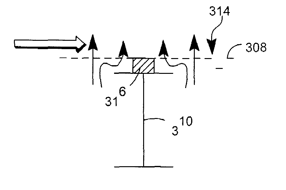
[0026]Referring to FIGS. 2-5, there is shown the present invention which raises a vapor-liquid contacting tray above the supports. A spacing element 316 is situated between the support beam 310 and the vapor-liquid contacting tray 308 to create a gap for additional vapor flow, effectively reducing the dead zone area.

[0027]The vapor-liquid contacting tray 308 is perforated with perforations 314 to allow vapor to flow through the vapor-liquid contacting tray 308 and contact the liquid on the vapor-liquid contacting tray 308. The perforations 314 may be any shape or size hole or slot; or any other device known in the art, including valves or bubble caps, that allow vapor passage. In general, the number and size of perforations are chosen to be small enough to avoid excessive liquid flow down through the perforations, and large enough to avoid any excessive pressure drop.

[0028]Vertical space for froth movement may be decreased due to the support beams of superior vapor-liquid contacting...

second embodiment

[0033]Referring to FIGS. 10A-10C, two alternative embodiments are shown to raise the vapor-liquid contacting tray above the supports. In the present invention, spacing element 422 is affixed to the support ring 404 such that the vapor-liquid contacting tray 408 is elevated above the support ring 404, thus activating a large portion of the perforations 414 directly above the support ring 404. Although spacing element 422 may create new dead zones by blocking some perforations 414 on the vapor-liquid contacting tray 408 that are not above the support ring 404, the total active area of the vapor-liquid contacting tray 408 is greater than if the vapor-liquid contacting tray 408 rested directly on the support ring 404. Additional support means 411 for spacing element 422 may be extended to the downcomer 406, the column wall 402 or the support ring 404 so as to provide additional rigidity to the spacing element 422 or vapor liquid contacting tray 408. In one particular embodiment, a gap b...

third embodiment

[0034]In the present invention, a movable support plate 409 is affixed to the support ring 404, and provides support for the downcomer 406. The movable support plate 409 is easily movable so as to simply adjust the elevation of the downcomer 406. This may be accomplished by numerous means such as utilizing elliptical shaped fastening holes in the movable support plate 409, in which fastening means such as a bolt may pass through allowing for easy adjustments. A U-shaped support bridge 420 is affixed to the movable support plate 409 to support the vapor-liquid contacting tray 408 above the support ring 404, thus activating a large portion of the perforations 414 directly above the support ring 404. Elevating the contacting tray 408 leaves an empty space between the downcomer 406 and the wall of the column that would otherwise be taken up by the movable support plate 409. A perforated end plate insert 405 may be inserted into this space to provide an additional active area for vapor-l...


PUM

PropertyMeasurementUnit
internal diameteraaaaaaaaaa
widthaaaaaaaaaa
width×height×lengthaaaaaaaaaa

Abstract

The invention involves a spacing element situated between a vapor-liquid contacting tray and a tray support to reduce the dead zone typically caused by the tray supports blocking of the perforations in the vapor-liquid contacting tray directly above the tray support.

Description

FIELD OF THE INVENTION[0001]This invention relates to vapor-liquid contacting apparatus for mass or heat transfer and specific features that improve the efficiency and capacity of this operation. The invention therefore relates to, for example, apparatus used as fractionation trays within fractional distillation columns. The invention may also be used in a variety of other gas-liquid contacting operations such as stripping or absorption processes.BACKGROUND OF THE INVENTION[0002]Vapor-liquid contacting devices are used in a wide variety of applications for separating liquid or vapor mixtures. One of the major applications of the vapor-liquid contacting devices is in the separation of chemical compounds via fractional distillation. These devices are also used to contact a gas stream with a treating liquid which selectively removes a product compound or an impurity from the gas stream.[0003]Within a column containing vapor-liquid contacting devices, liquid flows in a generally downwar...

Claims


Application Information

Patent Timeline
Patent Type & Authority Patents(United States)
IPC IPC(8): B01F3/04
CPCB01D3/326B01D3/328Y10T29/49826
Inventor XU, ZHANPINGRICHARDSON, KEVIN A.MILLER, ROBERT J.URBANSKI, NICHOLAS F.
Owner UOP LLC
Why Eureka
Try Eureka