Optical connection switching apparatus and management control unit thereof

a technology of optical connection and management control unit, which is applied in data switching networks, multiplex communication, fault recovery arrangements, etc., can solve the problems of link switching not being able to achieve the normal connection, need to take a large number of processes, and complicated operations, so as to reduce the time needed for this operation, shorten the time needed, and reduce the cost of operation managemen

Inactive Publication Date: 2010-10-12
FUJITSU LTD
View PDF22 Cites 5 Cited by
  • Summary
  • Abstract
  • Description
  • Claims
  • Application Information

AI Technical Summary

Benefits of technology

[0025]The present invention has been developed with a view to eliminating the above-mentioned problems, and it is therefore an object of the invention to provide an optical connection switching apparatus and a management control unit therefor capable of acquiring the information on equipment having an optical communication interface to be optically connected, for carrying out the automatic connection management on this equipment. In addition, another object of the present invention is to improve the reliability in the case of the incorporation of these apparatus and unit into a network system.
[0036]According to the present invention, the optical connection switching facility is controlled to make the connection between the optical input / output port connected to the optical transmitting / receiving unit and the optical input / output port connected to the equipment so that the communication is made with the connected equipment through the use of the optical transmitting / receiving unit to acquire and manage the information on the equipment, thus automating the connection management on the connected equipment to considerably shortening the time needed for this operation, which can considerably reduce the operation management cost as a result.
[0037]Moreover, the connection, disconnection or communication state of the equipment can be monitored by monitoring the optical power information on the optical input / output port of the optical connection switching facility, which can achieve the automation of the inter-port connection switching and which can also automate the connection switching at the re-construction of a network using this optical connection switching apparatus or at the occurrence of a trouble. This can considerably reduce the time needed for this operation and can cut the operation management cost of the network.
[0038]Still moreover, when an optical connection switching apparatus is placed into a redundant condition according to the present invention, the speeding-up of the detection of a trouble point based on a detection in a physical layer becomes feasible. In addition, since the switching becomes possible by making reference to identification information (for example, address information) on equipment, the switching to a spare system becomes easily and quickly achievable. Still additionally, the employment of the above-described technique can shorten the system-down time and the time needed for the switching to the spare system, which can shorten the suspension time of the system and enhance the reliability of the network system.

Problems solved by technology

In general, the construction and change of a network system or the change of the connection of optical fibers stemming from the occurrence of a trouble lead to complicated operations such as optical fiber connection device confirmation tagging, connection diagram renewal and connection confirmation.
Such a network environment management method creates a problem in that there is a need to take a large number of processes.
Although this requires monitoring the contents of an optical signal, it is impossible, for that the existing optical connection switching apparatus is not designed to analyze the contents of an optical signal while conducting the route switching in a state of the optical signal.
Therefore, in the case of the conventional switching to a spare apparatus at the occurrence of a trouble, since the frequency of change of the apparatus to be connected is high, there is a high possibility that only the link switching cannot achieve the normal connection.
Moreover, since the control in the physical layer is principally conduced instead of the control in the layer 3 such as a routing table, a redundancy protocol for a router cannot cope with it and, hence, a new switching procedure becomes necessary.
Still moreover, in the case of the employment of a protection table (port information), an increase in the number of ports causes a complicated management and then leads to a low reliability.

Method used


Image

  • Optical connection switching apparatus and management control unit thereof
  • Optical connection switching apparatus and management control unit thereof
  • Optical connection switching apparatus and management control unit thereof

Examples


Embodiment Construction

[A] Description of Embodiment

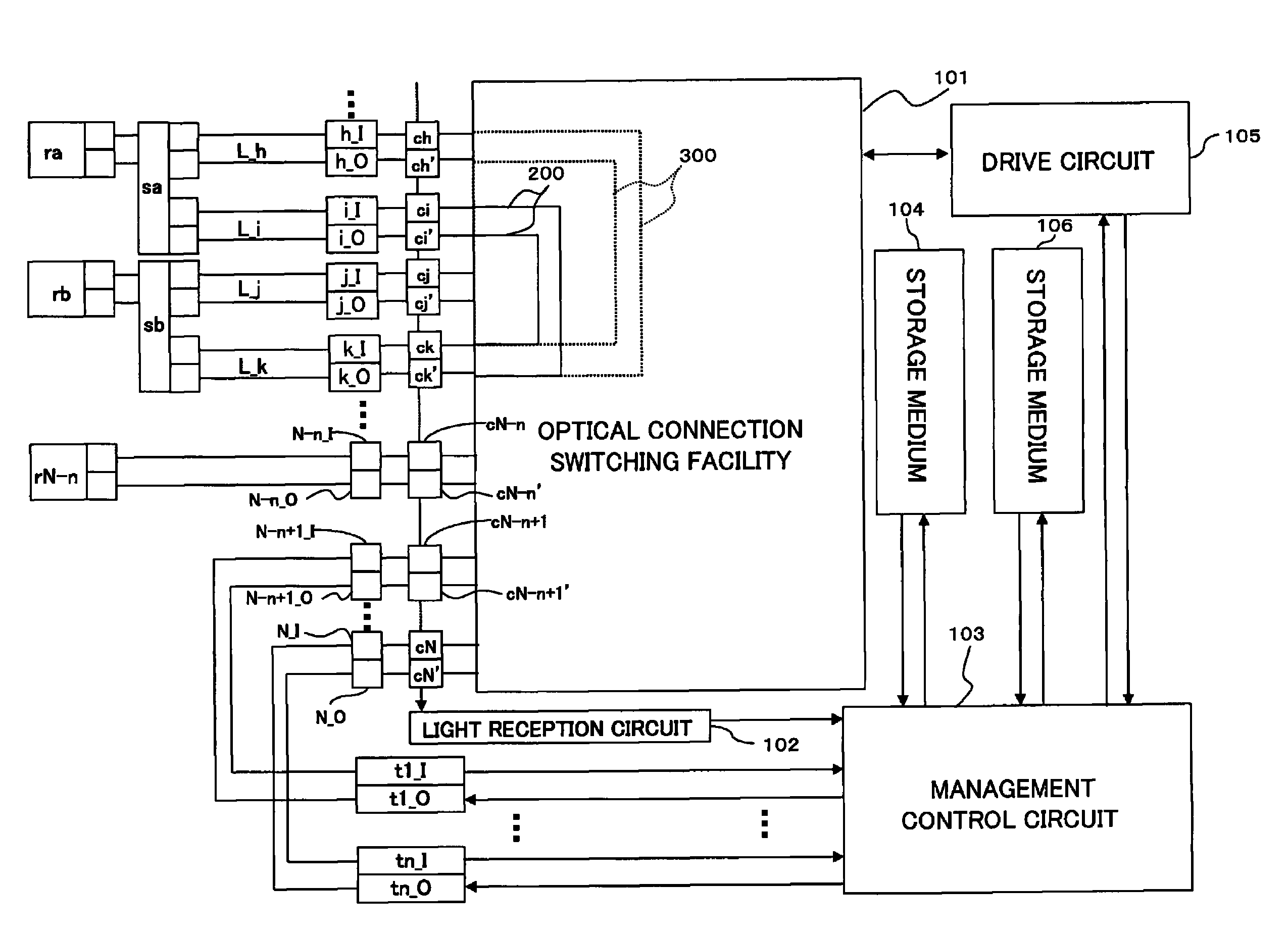
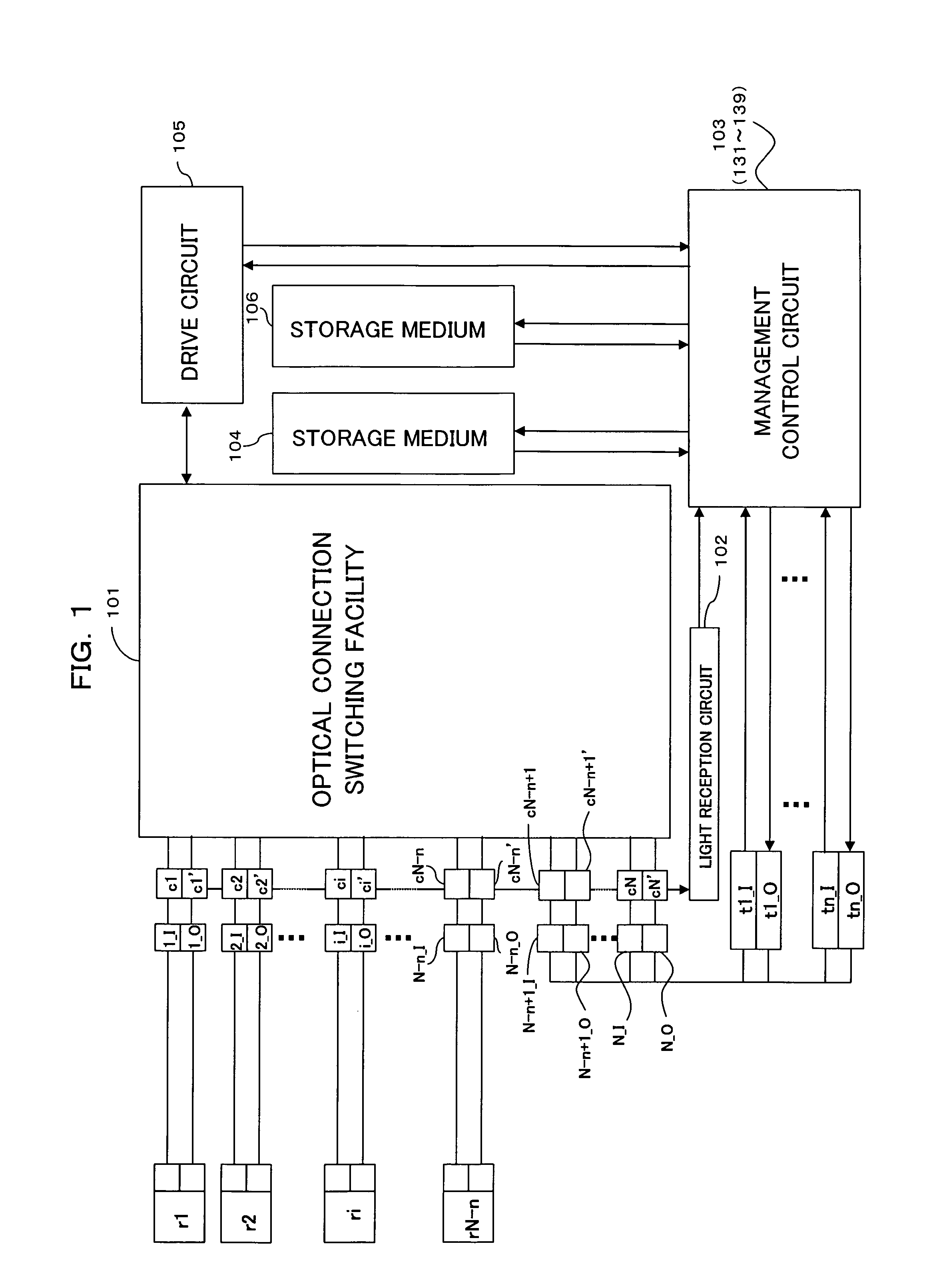
[0085]FIG. 1 is a block diagram showing a configuration of an optical connection automatic-switching apparatus according to an embodiment of the present invention. In FIG. 1, the optical connection automatic-switching apparatus is made up of optical input ports 1_I, 2_I, . . . , N-n_I and optical output ports 1_O, 2_O, . . . , N-n_O serving as a plurality (N-n) of sets of IT equipment connection ports which come into connection with a plurality of IT equipment (information equipment) r1, r2, . . . , rN-n (N≧2, 1≦n1 and optical output ports N-n+1_O, . . . , N_O serving as n sets of control ports corresponding to the number of types of handled interfaces of the IT equipment r1, r2, . . . , rN-n, an optical connection switching facility (optical switch) 101 connected through optical wiring (optical fibers) to the n sets of ports 1_I, 2_I, . . . , N_1 and 1_O, 2_O, . . . , N_O in total, a light reception circuit 102, a management control circuit 103, storage...


PUM


Abstract

An optical connection switching according to the present invention comprises an optical connection switching facility capable of making a connection between any one of optical input ports and any one of optical output ports, one or more optical transmitting / receiving units connected to a portion of the optical input / output ports, and management control units for controlling the optical connection switching facility to make a connection between the optical input / output port connected to the optical transmitting / receiving unit and the optical input / output port connected to equipment for acquiring and managing information on the equipment by making a communication with the equipment through the use of the optical transmitting / receiving unit. This enables acquiring the information on the equipment having an optical communication interface to be optically connected, thereby automating the connection management of the equipment.

Description

CROSS REFERENCE TO RELATED APPLICATIONS[0001]This application is a continuation-in-part application of application Ser. No. 10 / 873,257, filed Jun. 23, 2004, now abandoned.[0002]This application is based on and hereby claims priority to Japanese Applications No. 2004-100796 filed on Mar. 30, 2004 and No. 2005-20129 filed on Jan. 27, 2005 in Japan, the contents of which are hereby incorporated by reference.BACKGROUND OF THE INVENTION[0003](1) Field of the Invention[0004]The present invention relates to an optical connection (wiring) switching apparatus and a management control unit thereof, for example, an optical connection switching apparatus and a management control unit thereof suitable for the connection management in in-datacenter or in-company optical network or the like.[0005](2) Description of the Related Art[0006]Along with the recent speeding-up of transmission signals and wide-spreading of networks, an optical signal network is being constructed which employs, as a transmi...

Claims


Application Information

Patent Timeline
Patent Type & Authority Patents(United States)
IPC IPC(8): H04J14/00H04B10/03H04B10/032H04B10/27H04L12/70H04L12/931H04Q11/00
CPCH04Q11/0005H04Q2011/0039H04Q2011/0079
Inventor AMEMIYA, KOUICHIROUNAITO, TAKAOKATAGIRI, TORUTANAKA, TOSHIKI
Owner FUJITSU LTD
Why Eureka
Try Eureka