
Systems and methods for employing an FFT to distinguish R-waves from T-waves using an implantable medical device

a medical device and fft technology, applied in the field of implantable medical devices, can solve the problems of ventricular fibrillation, vf, if not terminated, fatal, difficult to distinguish r-waves from t-waves, etc., to facilitate reliable detection of vt/vf, reduce or eliminate t-wave oversensing, and eliminate further t-wave oversensing

Inactive Publication Date: 2010-10-12
PACESETTER INC
View PDF27 Cites 39 Cited by
  • Summary
  • Abstract
  • Description
  • Claims
  • Application Information

AI Technical Summary

Benefits of technology

[0014]Exemplary techniques are also provided for detecting T-wave oversensing once R-waves have been distinguished from T-waves based on their spectral components. In one example, the implanted device detects sequences of alternating R-waves and T-waves in tachycardia-filtered signals (i.e. within signals that should exhibit only R-waves). The device associates such a sequence of alternating R-waves and T-waves as being indicative of T-wave oversensing and adjusts the sensitivity of the tachycardia filter in an attempt to eliminate further T-wave oversensing.
[0015]Thus, a variety of techniques are provided for reliably distinguishing between R-waves and T-waves so as to reduce or eliminate T-wave oversensing and thereby facilitate reliable detection of VT / VF. The various techniques can be selectively combined to further improve the specificity with which R-waves and T-waves are distinguished. For example, both power-based and LDA-based techniques may be exploited. The various techniques may be implemented, where appropriate, as systems, methods or other appropriate embodiments.

Problems solved by technology

However, some tachycardias, particularly ventricular tachycardia, can trigger ventricular fibrillation (VF) wherein the heart beats chaotically such that there is little or no net flow of blood from the heart to the brain and other organs.
VF, if not terminated, is fatal.
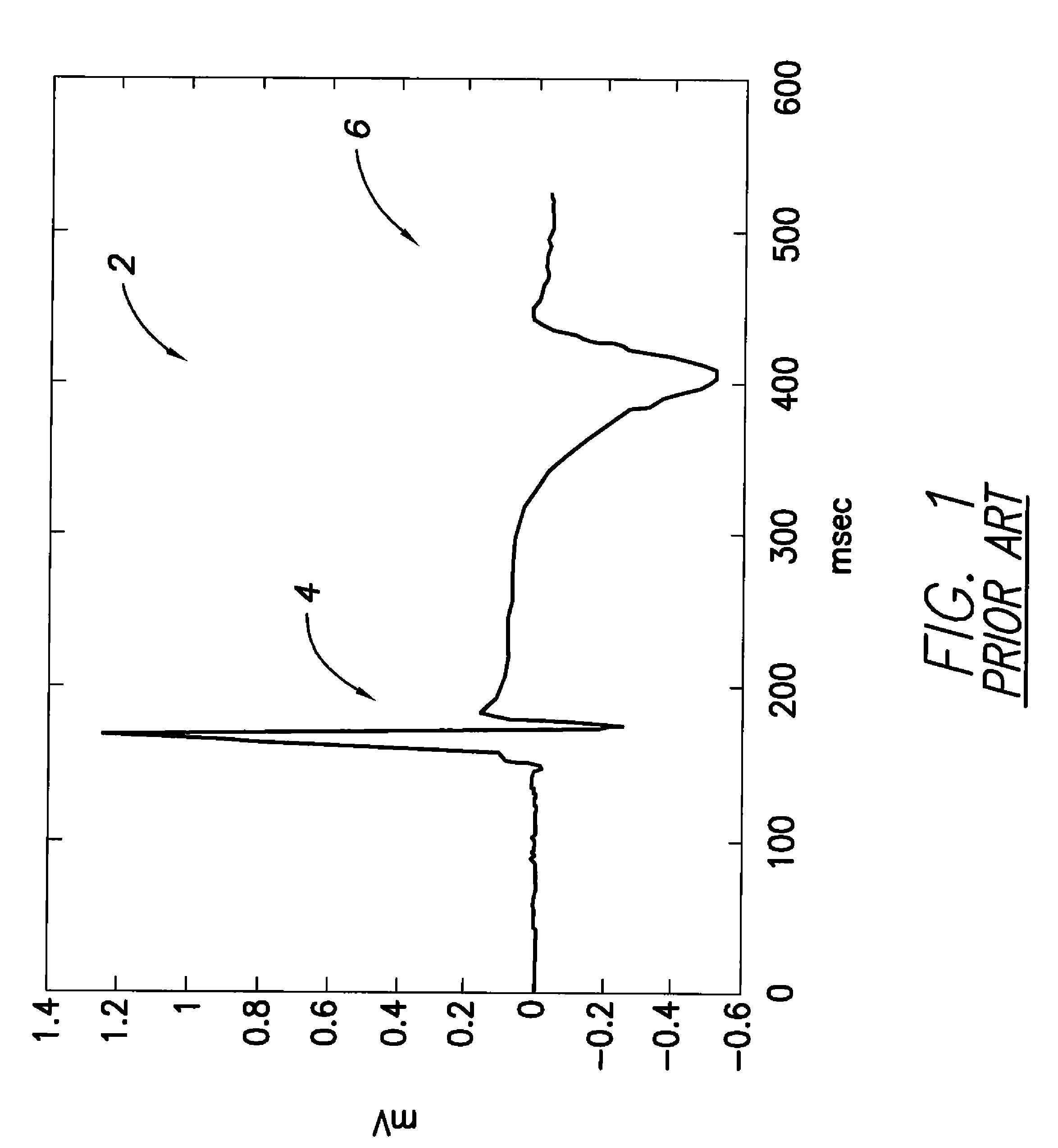
Accordingly, it can be difficult to distinguish R-waves from T-waves from the wideband-filtered signals so as to obtain an accurate measure of the ventricular rate, and so it can be difficult to reliably detect either bradycardia or tachycardia from the wideband-filtered signals.
As can be appreciated, T-wave oversensing is a significant concern since misidentification of T-waves as R-waves can result in significant miscalculation of the true heart rate within the patient, causing therapy to be delivered when not warranted or potentially causing therapy to be withheld even when needed.
This is due to the fact that the frequencies associated with the fast R-waves of interest during VT are also associated with T-waves, and hence the filter cannot eliminate all T-waves while still retaining the R-waves.
This is difficult, at best, since the relative magnitudes of the R-waves and T-waves may change significantly over time within the patient, perhaps due to the use of medications or due to physiological or anatomical changes in the heart brought on by medical conditions, such as cardiac ischemia, myocardial infarctions, congestive heart failure, etc.
Hence, T-wave oversensing is a significant problem within the tachycardia-filtered signals.
If T-wave oversensing occurs, the ventricular rate cannot be accurately and reliably measured based solely on the output of the tachycardia filter (at least at the high rates associated with VT / VF), and hence problems arise in the detection of VT, VF or other forms of ventricular tachyarrhythmia.
Failure to properly detect VT / VF when it is present can result in a failure to deliver appropriate therapy.
False detection of VT / VF when it is not present can result in delivery of inappropriate therapy.

Method used


Image

  • Systems and methods for employing an FFT to distinguish R-waves from T-waves using an implantable medical device
  • Systems and methods for employing an FFT to distinguish R-waves from T-waves using an implantable medical device
  • Systems and methods for employing an FFT to distinguish R-waves from T-waves using an implantable medical device

Examples


Embodiment Construction

[0032]The following description includes the best mode presently contemplated for practicing the invention. This description is not to be taken in a limiting sense but is made merely to describe general principles of the invention. The scope of the invention should be ascertained with reference to the issued claims. In the description of the invention that follows, like numerals or reference designators are used to refer to like parts or elements throughout.

Overview of Implantable Medical System

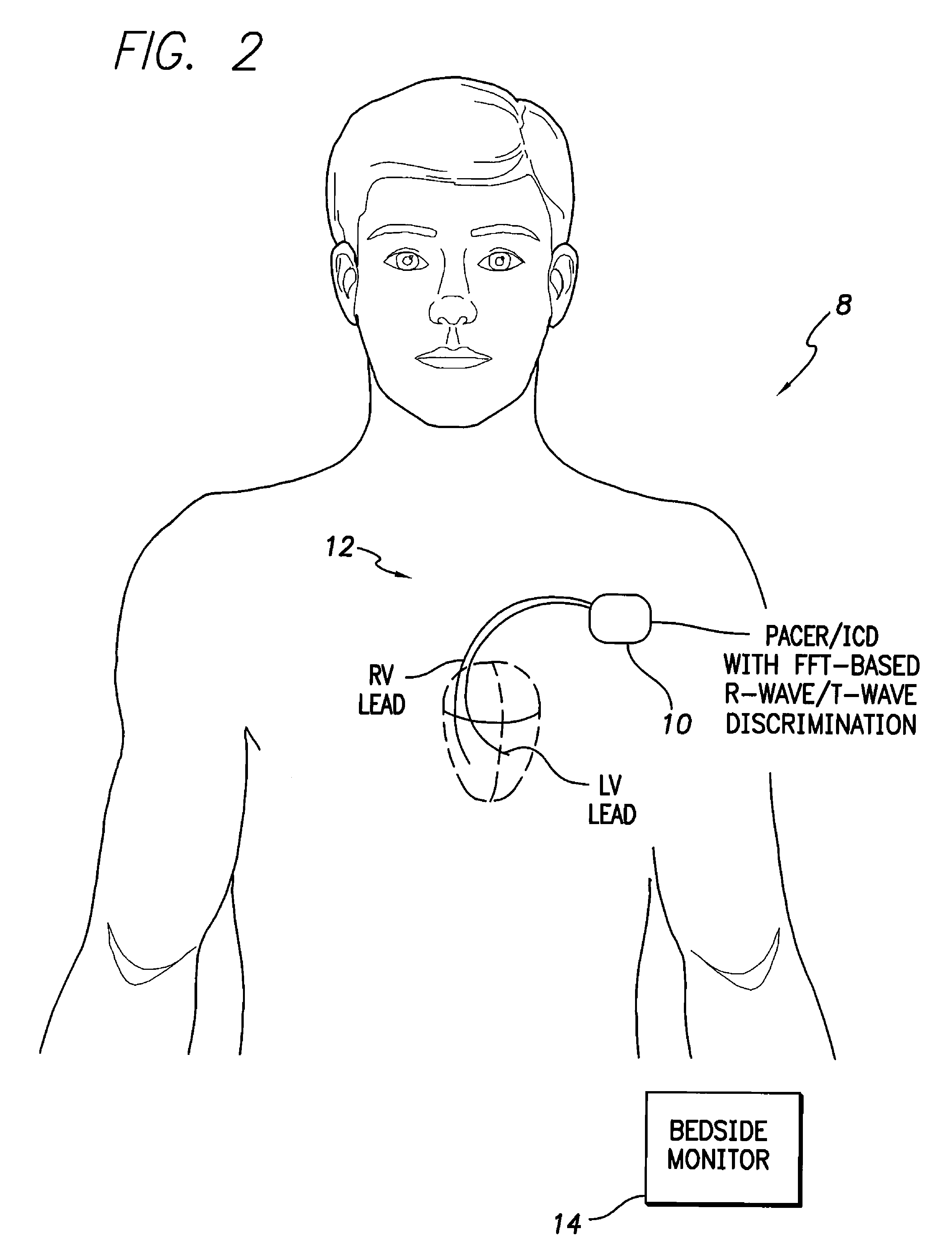
[0033]FIG. 2 illustrates an implantable medical system 8 having a pacer / ICD 10 that includes an FFT-based R-wave / T-wave discrimination system, i.e., a system capable of distinguishing R-waves from T-waves using an FFT or other device for converting time-domain waveforms to frequency-domain waveforms. To this end, pacer / ICD 10 receives voltage signals from various cardiac pacing / sensing leads 12 (only two of which are shown in the FIG. 2) from which various channels of IEGM signals are derived...


PUM


Abstract

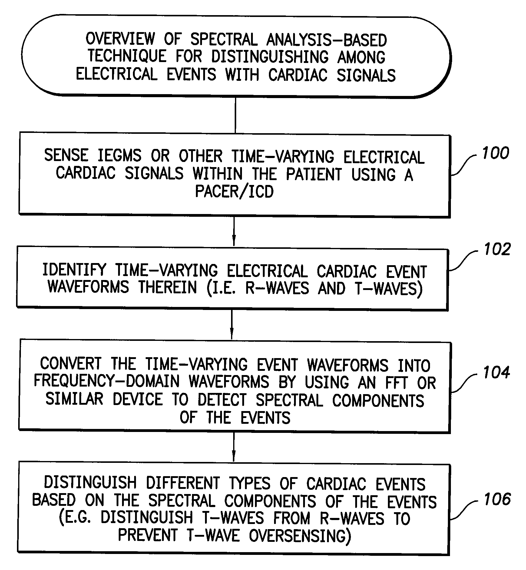
A Fast Fourier Transform (FFT) converts time-varying event waveforms into the frequency domain waveforms to thereby decompose the events into their spectral components, which are analyzed to distinguish R-waves from T-waves. In some embodiments, the FFT is only activated if a ventricular tachyarrhythmia is already indicated. For example, an initial ventricular rate may be derived from a ventricular IEGM based on all events detected therein. The initial ventricular rate is compared against one or more thresholds representative of ventricular tachycardia (VT) and / or ventricular fibrillation (VF) to determine if VT / VF is indicated. If so, the FFT is activated to distinguish R-waves from T-waves and, in particular, to detect and eliminate T-wave oversensing. Then, the ventricular rate is re-determined based only on the rate of true R-waves. Therapy is delivered if VT / VF is still detected.

Description

CROSS-REFERENCE TO RELATED APPLICATIONS[0001]This application is related to copending U.S. patent application Ser. No. 11 / 841,243, filed concurrently herewith, titled “Systems and Methods for Employing an FFT to Detect Atrial Fibrillation Using an Implantable Medical Device”.FIELD OF THE INVENTION[0002]The invention generally relates to implantable medical devices such as pacemakers and implantable cardioverter / defibrillators (ICDs) and, in particular, to techniques for distinguishing R-waves from T-waves to prevent T-wave oversensing and to facilitate reliable detection of ventricular tachyarrhythmias.BACKGROUND OF THE INVENTION[0003]An arrhythmia is an abnormal heart beat pattern. One example of arrhythmia is bradycardia wherein the heart beats at an abnormally slow rate or wherein significant pauses occur between consecutive beats. Other examples of arrhythmia include tachyarrhythmias wherein the heart beats at an abnormally fast rate. With an atrial tachyarrhythmia, such as atri...

Claims


Application Information

Patent Timeline
IPC IPC(8): A61B5/0456A61B5/352
CPCA61B5/0452A61B5/7257A61B5/0464A61N1/3621A61B5/363A61B5/349
Inventor GILL, JONGBOILEAU, PETERBORNZIN, GENE A.
Owner PACESETTER INC
Learn More