Fuel-fired, power vented high efficiency water heater apparatus

a high-efficiency, water heater technology, applied in water heaters, water heaters, furnace-tube steam boilers, etc., can solve the problems of increasing the production cost of water heaters to an unacceptable extent, and reducing the overall energy efficiency of water heaters

Active Publication Date: 2010-10-19
RHEEM MFG CO
View PDF40 Cites 11 Cited by
  • Summary
  • Abstract
  • Description
  • Claims
  • Application Information

AI Technical Summary

Benefits of technology

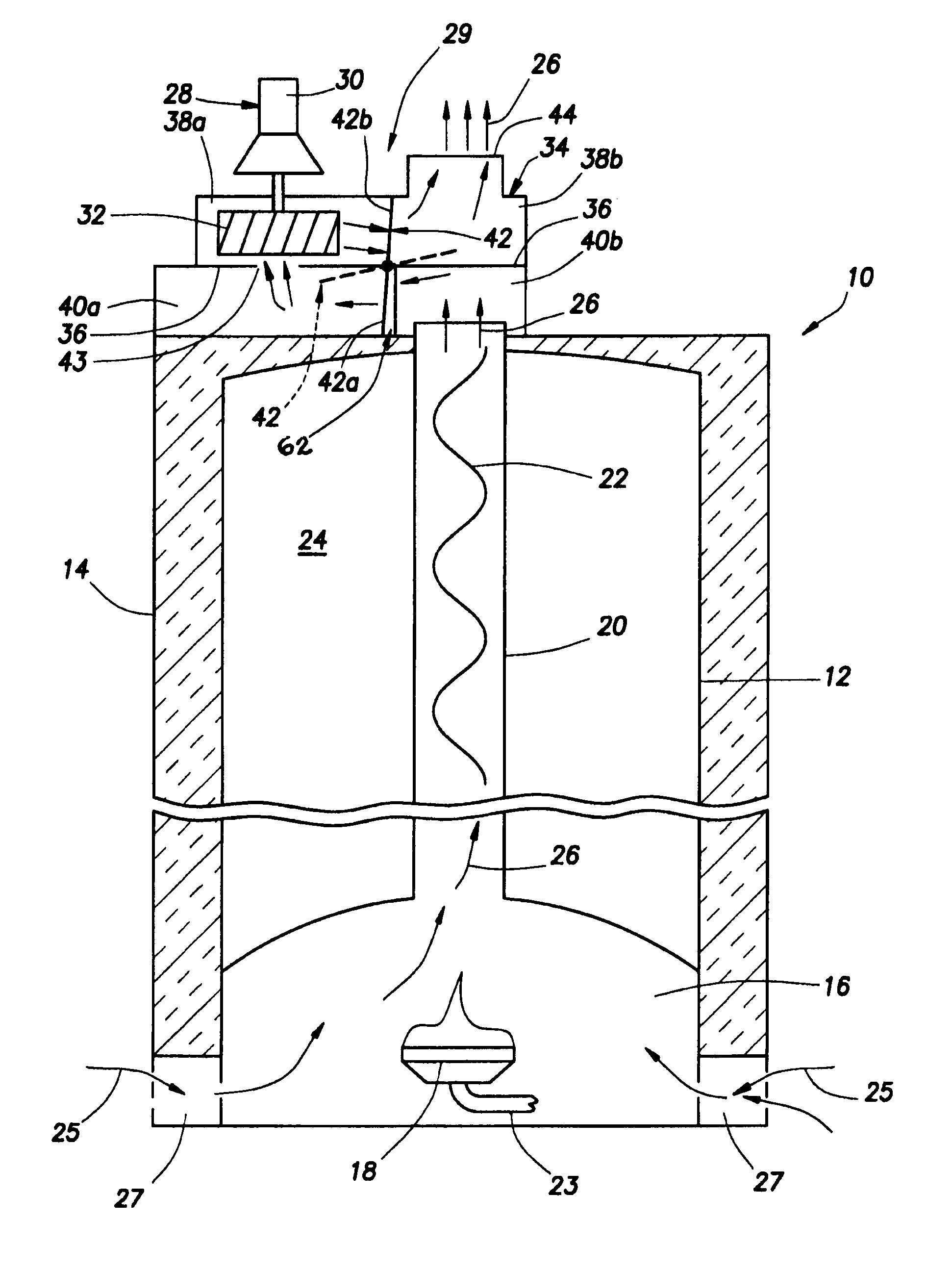
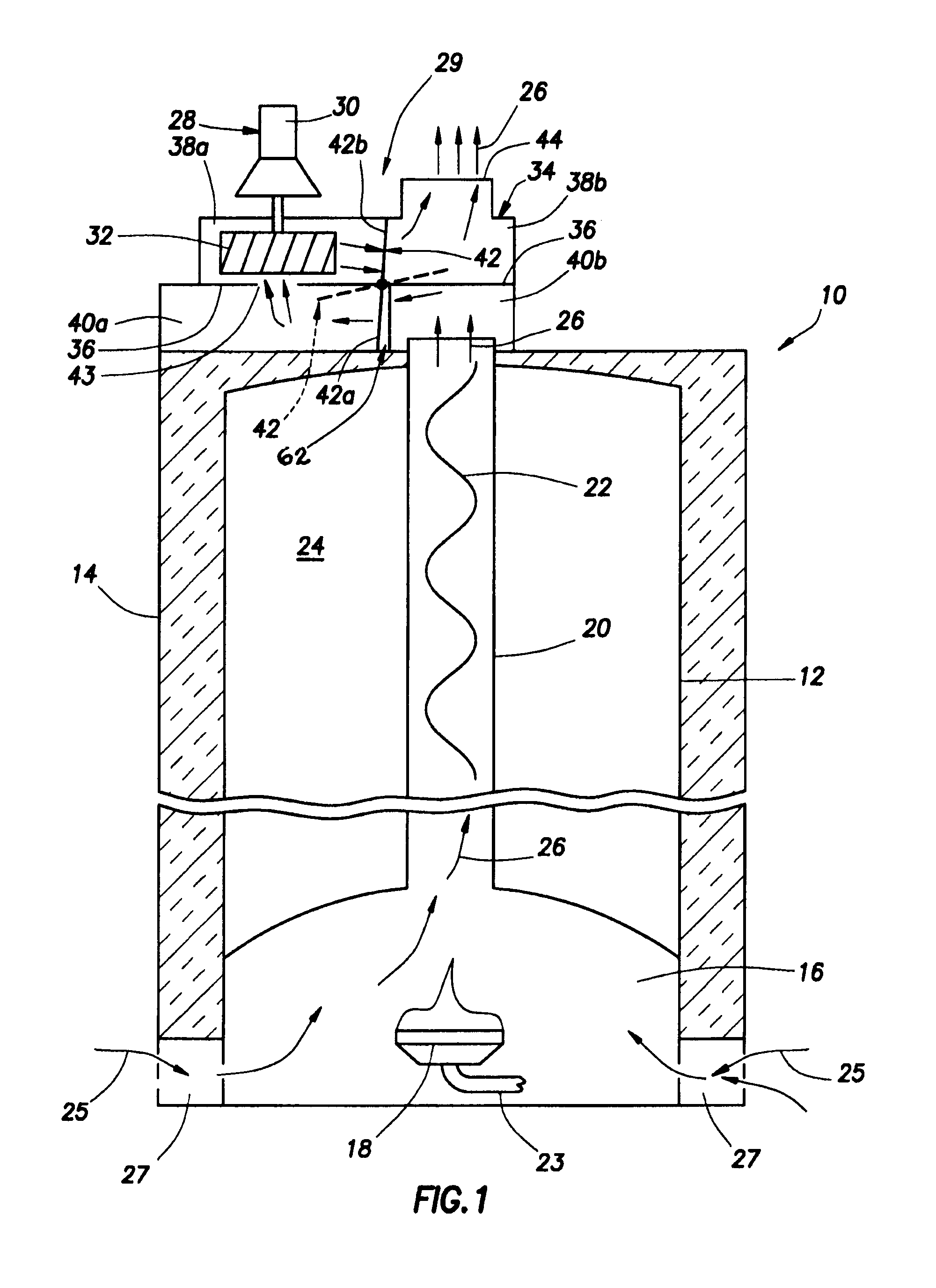
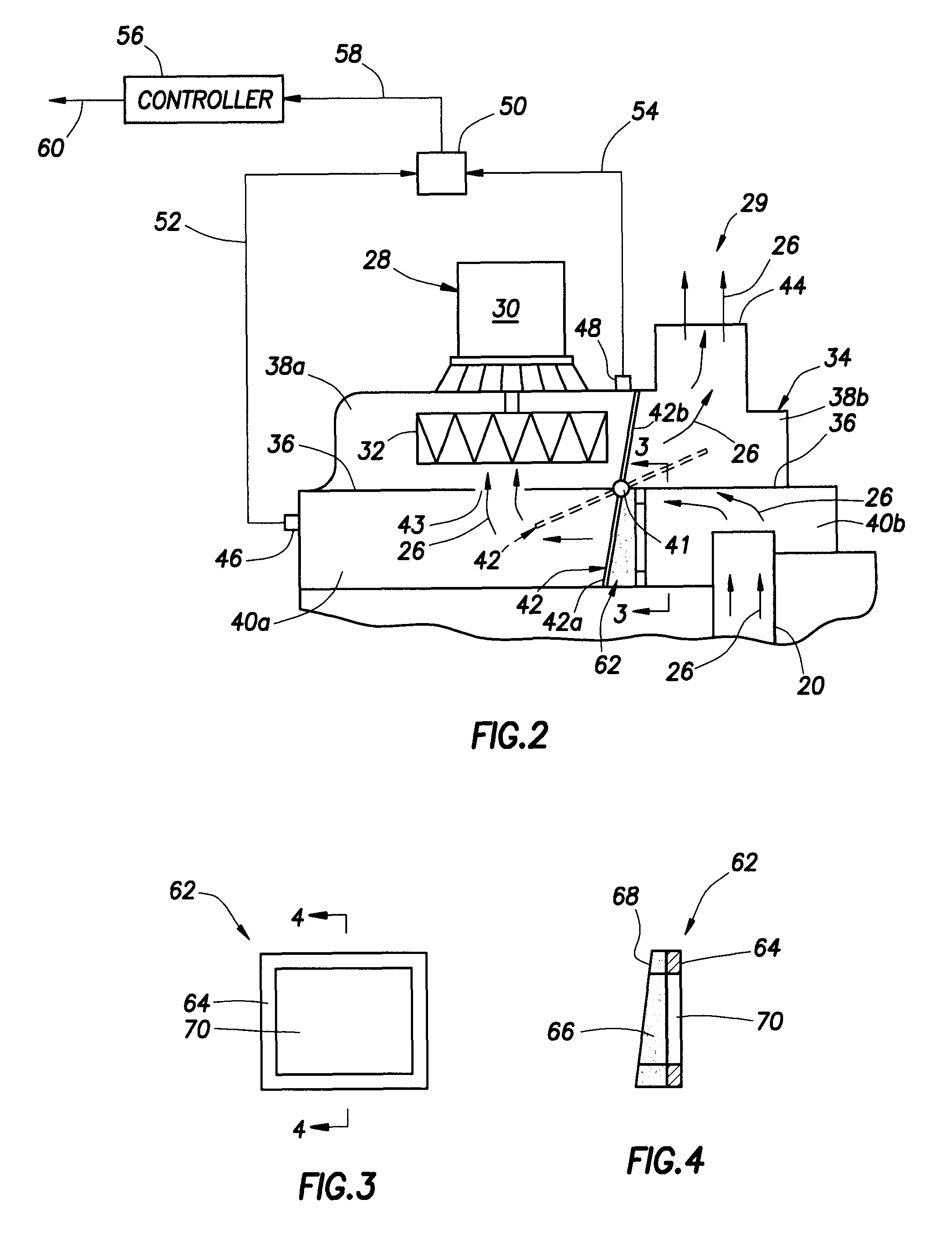
[0006]In an exemplary embodiment thereof, the draft inducer fan assembly comprises a housing having an internal wall structure dividing its interior into first and second chambers communicating with one another through an opening in the internal wall structure. The first chamber has an inlet area communicating with the flue to receive hot combustion gases therefrom, the housing further having an outlet area through which the received hot combustion gases may exit the housing. The assembly further comprises a draft inducer fan associated with the housing and operative to sequentially flow the received hot combustion gases from the first chamber through the internal wall structure opening into the second chamber and then outwardly from the housing through the outlet area. A damper portion of the assembly is movable, by fluid pressure force created by operation of the draft inducer fan, from a normally closed position thereof in which the damper substantially prevents gas flow between the housing inlet and outlet areas, to an open position in which the damper permits gas flow between the housing inlet and outlet areas. The damper preclusion of gas flow between the housing inlet and outlet areas substantially prevents convective flow of flue-heated air through the housing during non-firing “standby” periods of the water heater, thereby desirably increasing the overall energy efficiency of the water heater.
[0009]In another exemplary embodiment of the draft inducer fan assembly its internal housing wall structure opening is a first opening, and the internal wall structure further divides the interior of the housing into a third chamber separated from the first chamber and communicating with the second chamber through a second opening in the internal wall structure the housing has a dilution air inlet through which dilution air from an external source thereof may flow into the third chamber for transfer therefrom into the second chamber via the second opening. The damper blocks the first and second openings when the damper is in its normally closed position, and uncovers the first and second openings when the damper is in its open position. The draft inducer fan has a motor disposed within the third chamber and positioned to be impinged upon and cooled by incoming dilution air. In this exemplary embodiment of the draft inducer fan assembly the housing has an internal wall portion that cooperates with the damper, when it is in its normally closed position during standby periods of the water heater, to substantially prevent convective flow of flue-heated air outwardly through either the combustion gas outlet of the housing or its dilution air inlet.

Problems solved by technology

In the area of fuel-fired water heaters a continuing design challenge is the reduction of heat loss from the water heater, which causes an undesirable lessening of the overall energy efficiency of the water heater, during idle or “standby” periods of the water heater.
At such area, convective flows of flue-heated air rising from the water heater, or cold air downflows into the flue, can undesirably reduce the temperature of the tank-stored water, thereby correspondingly diminishing the overall energy efficiency of the water heater.
However, in various water heater applications, such as in the residential market, this addition of a motorized damper and associated controls to the water heater can increase the production cost of the water heater to an unacceptable extent.

Method used


Image

  • Fuel-fired, power vented high efficiency water heater apparatus
  • Fuel-fired, power vented high efficiency water heater apparatus
  • Fuel-fired, power vented high efficiency water heater apparatus

Examples


exemplary embodiment 292

[0029]A second exemplary embodiment 292 of the previously described draft inducer fan assembly 29 is schematically shown in FIG. 2A. With the two exceptions noted below, the fan assembly 292 is identical to the previously described fan assembly 29. For ready comparison of the two fan assemblies 29 and 292, identical or substantially similar components in the two fan assembly embodiments have been given identical reference numerals.

[0030]The first difference between the fan assemblies 29 and 292 is that, in the fan assembly 292, during firing of the water heater 10, and operation of the draft inducer fan 28, ambient dilution air 61 is drawn into the housing subchamber 40a, via dilution air openings 63 in the side wall of the housing 34, for mixing with and cooling of the hot combustion products 26 entering the subchamber 38a via the opening 43. The second difference between the fan assemblies 29 and 292 is that in the assembly 292 the pressure tap 46 is relocated as shown in FIG. 2A....

exemplary embodiment 293

[0035]A third exemplary embodiment 293 of the previously described draft inducer fan assembly 29 is schematically shown in FIG. 7. With the exception noted below, the fan assembly 293 is identical to the previously described fan assembly 29. For ready comparison of the two fan assemblies 29 and 293, identical or substantially similar components in the two fan assembly embodiments have been given identical reference numerals.

[0036]The difference between the fan assemblies 29 and 293 is that in the assembly 293 an additional damper stop / gasket structure 62 is operatively installed in the upper chamber 38 in a manner such that when the damper 42 is in its closed position its lower portion 42a sealingly engages the gasket material on the lower damper stop / gasket structure 62, and its upper portion 42b sealingly engages the gasket material on the upper damper stop / gasket structure 62. Thus, during standby periods of the water heater 10 undesirable upward convective heat flow from the flu...

exemplary embodiment 294

[0037]Schematically depicted in FIG. 8 is a fourth exemplary embodiment 294 of the previously described draft inducer fan assembly 29. Assembly 294 is operatively mounted on top of the previously described water heater 10, over the open upper end of its flue 20, and has a blower assembly housing 94 with an open bottom side that overlies the open upper end of the flue 20. Extending downwardly through a horizontally central portion of the assembly housing 94 into its interior is a fan impeller housing 96 in which the fan impeller 32 is rotatably disposed. As illustrated, the fan motor 30 is positioned to the right of the impeller housing 96 and is disposed within a dilution air receiving chamber portion 98 of the assembly housing 94.

[0038]A horizontal dividing wall 100 within the interior of the assembly housing 94 vertically divides a left interior portion thereof into a flue gas receiving chamber 102 disposed beneath the dividing wall 100, and a mixing chamber 104 disposed above the...


PUM


Abstract

A fuel-fired water heater has a draft inducer fan assembly with a housing having an inlet for receiving hot combustion gases discharged from the water heater, and an outlet for discharging the combustion gases. A normally closed damper member within the housing is openable by fluid pressure force created by operation of a draft inducer fan portion of the assembly. With the damper in its open position the fan exhausts the received combustion gases through a housing outlet. When the damper closes it prevents convective outflow through the housing outlet of flue-heated air. In alternate embodiments of the assembly the fan is operative to also draw in dilution air that cools the fan motor and the discharged combustion gases, with the assembly having an internal configuration preventing convective outflow of flue-heated air through the housing dilution air inlet during standby periods of the water heater.

Description

BACKGROUND OF THE INVENTION[0001]The present invention generally relates to fuel-fired heating appliances and, in a representatively illustrated embodiment thereof, more particularly relates to a fuel-fired water heater having incorporated therein a specially designed draft inducer fan assembly that substantially reduces undesirable heat loss from the water heater during standby periods thereof, thereby desirably increasing the overall energy efficiency of the water heater.[0002]In the area of fuel-fired water heaters a continuing design challenge is the reduction of heat loss from the water heater, which causes an undesirable lessening of the overall energy efficiency of the water heater, during idle or “standby” periods of the water heater. A substantial portion of the standby period heat loss from tank type water heaters occurs at the flue gas discharge area thereof. At such area, convective flows of flue-heated air rising from the water heater, or cold air downflows into the flu...

Claims


Application Information

Patent Timeline
Patent Type & Authority Patents(United States)
IPC IPC(8): F22B9/18
CPCF24H1/205F24H9/0031
Inventor YIN, JIANGBOROS, JOZEF
Owner RHEEM MFG CO
Why Eureka
Try Eureka