Supercharge Your Innovation With Domain-Expert AI Agents!

Processing unit

a technology of processing unit and processing device, which is applied in the direction of mixing, chemistry apparatus and processes, mixers, etc., can solve the problems of reducing the capacity of shears

Active Publication Date: 2010-10-19
MERCK LIFE SCI AB
View PDF18 Cites 24 Cited by
  • Summary
  • Abstract
  • Description
  • Claims
  • Application Information

AI Technical Summary

Benefits of technology

"The invention is a processing device that uses a magneto drive to transmit power from an external drive unit to an internal processing unit without using a shaft. The processing unit has a rotating inner part and a stationary outer part with shearing recesses that cut and mix products. The device is designed to be easy to clean, minimize contamination, and has a long life. The processing unit is supported by a bearing and rotor, and can rotate at high speeds. The technical effects of the invention include compact design, effective processing, and minimized risk of contamination."

Problems solved by technology

There is a constant and well-known problem with this type of rotary seals in the sense that they are constantly exposed to wear, which results in particle generation, and without previous warning start to leak during the process.
In most cases this leakage results in microbial and / or particulate contamination of the products that are being processed and, thus, causes in most cases a total loss of the entire product batch.
A further problem of prior-art processing devices is that they have hidden cavities in the stuffing boxes and have long drive shaft supports, which practically cannot be cleaned in situ.
In many applications, especially in the pharmaceutical and biotechnology industry, this problem can be disastrous if it is not taken care of.
The problem may cause cross-contamination of various infected products between the batches.
In most cases this results in loss of the batch.

Method used


Image

  • Processing unit
  • Processing unit
  • Processing unit

Examples


Embodiment Construction

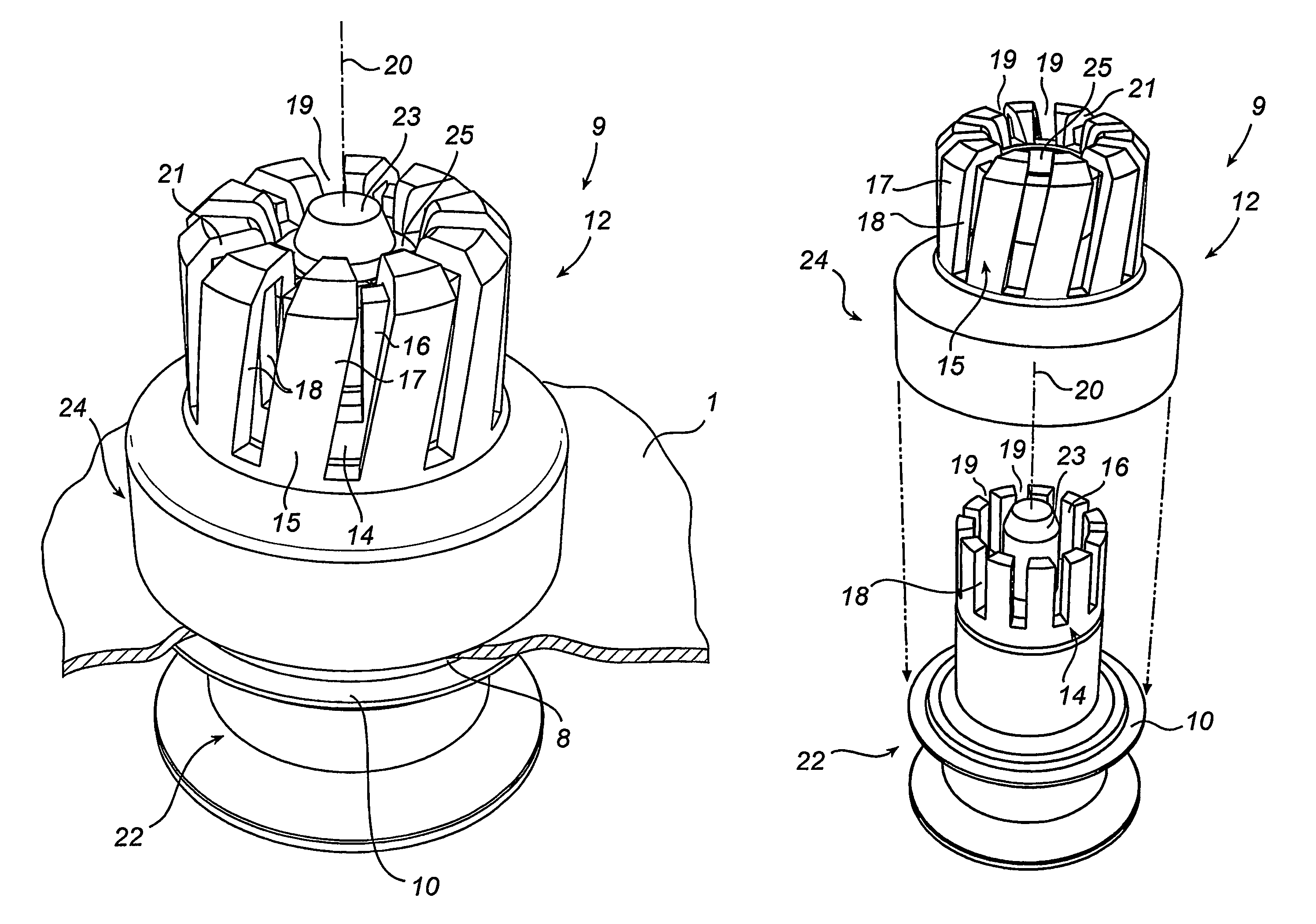
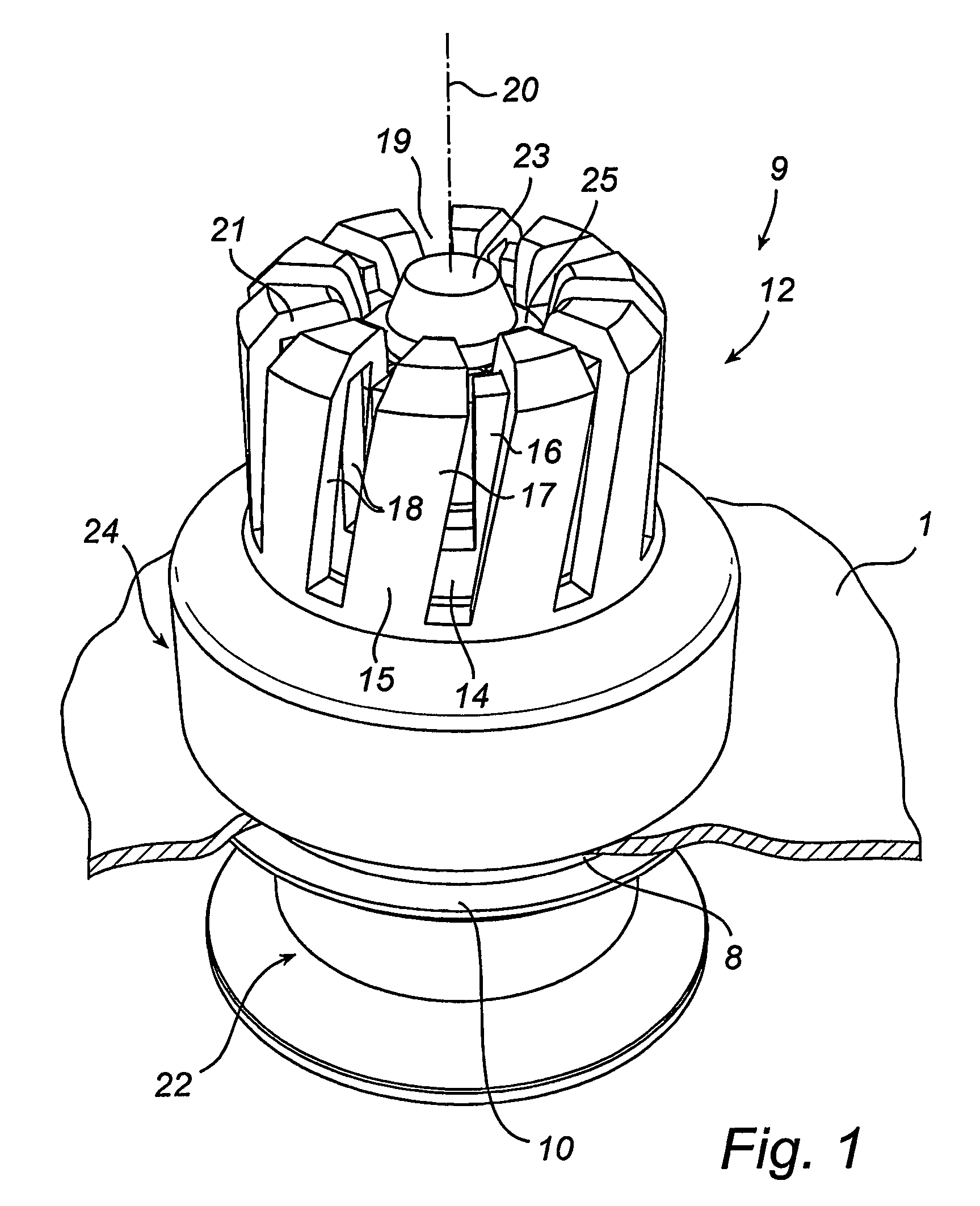
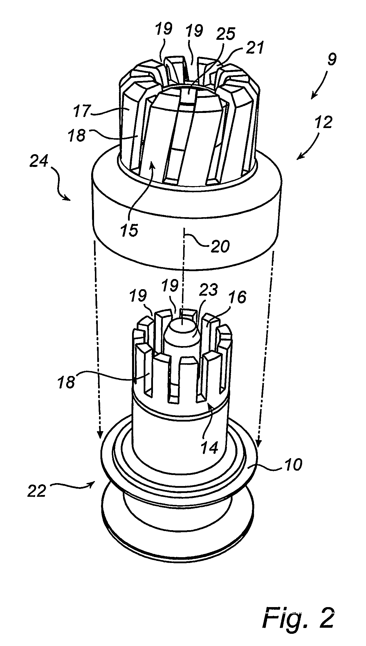
[0020]FIG. 3 illustrates a process vessel generally designated 1 and intended for processing products 2, in the case shown preferably by shearing products 3 for example in the form of clusters and / or materials into smaller particles and dispersing them in a more or less liquid product bulk 4. Alternatively, it is possible to mix, in a manner not shown in detail, in the process vessel 1 more or less liquid products which are difficult to mix. Of course, further applications are conceivable within the scope of the inventive concept.

[0021]The process vessel 1 suitably consists of a closed tank of sheet metal or some other metal or plastic, preferably stainless steel or the like. The process vessel 1 is usually positioned vertically and has at its top a manhole cover 5 for access to the interior of the process vessel for, for example, exchange and cleaning of interior components (see below) etc. The process vessel 1 has also at its top an inlet 6 for supplying the product or products 3 ...


PUM

PropertyMeasurementUnit
areaaaaaaaaaaa
speedaaaaaaaaaa
driving forceaaaaaaaaaa

Abstract

A device for cutting / shearing in a process vessel (1) product clusters and / or materials (3) into smaller particles and dispersing them in a liquid product bulk (4) or for mixing in the process vessel liquid products with each other that are difficult to mix. The device has an electric motor (13) arranged out-side the process vessel and, driven by the same by magneto drive, a processing unit (12) positioned inside the process vessel. The processing unit comprises a stationary inner part (14) and, rotatable about this, an outer part (15), the inner and outer parts having the shape of substantially concentric rings (16, 17) arranged with a close fit to each other and having a plurality of through slotshaped shearing recesses (18) opposing each other. The products that are to be cut / shorn and / or mixed are suppliable to the area of the common centre axis (20) of the rings and are thrown out through the shearing recesses while being shorn into pieces in order to leave the processing unit through the ring of the outer part, which ring also contributes to rotating the products in the process vessel around the processing unit.

Description

TECHNICAL FIELD[0001]This invention relates to a unit or device for processing products in a process vessel, especially for cutting / shearing product clusters and / or materials into smaller particles and dispersing them in a more or less liquid product bulk or for mixing therein more or less liquid products with each other which are difficult to mix, said device having a drive unit positioned outside the process vessel and a processing unit driven by the drive unit and positioned inside the process vessel.BACKGROUND ART[0002]In the liquid processing industry, such as the food, beverage, pharmaceutical and biotechnology industry, processing devices such as emulsifiers, homogenisers and mixers have been used for many years in certain steps of the production process. They are often intended for shearing of the products. The purpose of such shearing is above all to shear product clusters and / or materials into smaller particles and disperse them in a more or less liquid product bulk. The p...

Claims


Application Information

Patent Timeline
Patent Type & Authority Patents(United States)
IPC IPC(8): B01F7/02B01F13/08B01FB01F27/74B01F27/94
CPCB01F3/0807B01F3/0853B01F3/1221B01F7/162B01F7/163B01F13/0827B01F23/43B01F23/41B01F23/53B01F27/811B01F27/808B01F33/4535B01F33/453
Inventor MYHRBERG, LENNARTERIKSSON, CRISTIAN
Owner MERCK LIFE SCI AB
Features
  • R&D
  • Intellectual Property
  • Life Sciences
  • Materials
  • Tech Scout
  • Unparalleled Data Quality
  • Higher Quality Content
  • 60% Fewer Hallucinations
Learn More