System and method for steering the directional response of a microphone to a moving acoustic source

a technology of directional response and microphone, which is applied in the direction of direction/deviation determination system, using reradiation, instruments, etc., can solve the problems of internal acoustic time delay, acoustic source may periodically move, diaphragm vibrating, etc., to reduce the timeframe at which samples are taken, accurate delay and filter weighting coefficient, and accurate processing of electrical signals outpu

Active Publication Date: 2010-10-19
ZEBRA TECH CORP
View PDF18 Cites 71 Cited by
  • Summary
  • Abstract
  • Description
  • Claims
  • Application Information

AI Technical Summary

Benefits of technology

[0013]In addition to determining the angle of impingement, it may also be necessary to determine the frequency of the acoustic signal. In a far field setting, attenuation of an acoustic signal can vary depending on its frequency. Knowing both the angle of impingement and frequency can thereby allow the execution engine to provide a more accurate processing of electrical signals output from each of the corresponding two or more microphones arrangement.
[0014]The signal parameters, such as angle of incidence and frequency, allow the execution unit to derive more accurate delay and filter weighting coefficients. Those coefficients are then used by a delay element and tunable filter, whose outputs are mixed with the microphone transducer outputs to steer the directional polar response along an angle at which the acoustic wave impinges upon the microphones.
[0015]Rotating the radial axis of the directional response so that the radial axis now substantially aligns with the angle of impingement ensures that the unidirectional microphones can achieve a maximum SNR. The radial axis is periodically updated based on the frequency at which samples are taken. If, for exam

Problems solved by technology

Pressure upon that sealed volume from any direction around the diaphragm will cause the diaphragm to vibrate.
In addition, the acoustic wave from a forward direction will strike the back surface after it strikes the front surface, causing an internal acoustic time delay.
Unfortunately

Method used


Image

  • System and method for steering the directional response of a microphone to a moving acoustic source
  • System and method for steering the directional response of a microphone to a moving acoustic source
  • System and method for steering the directional response of a microphone to a moving acoustic source

Examples


Embodiment Construction

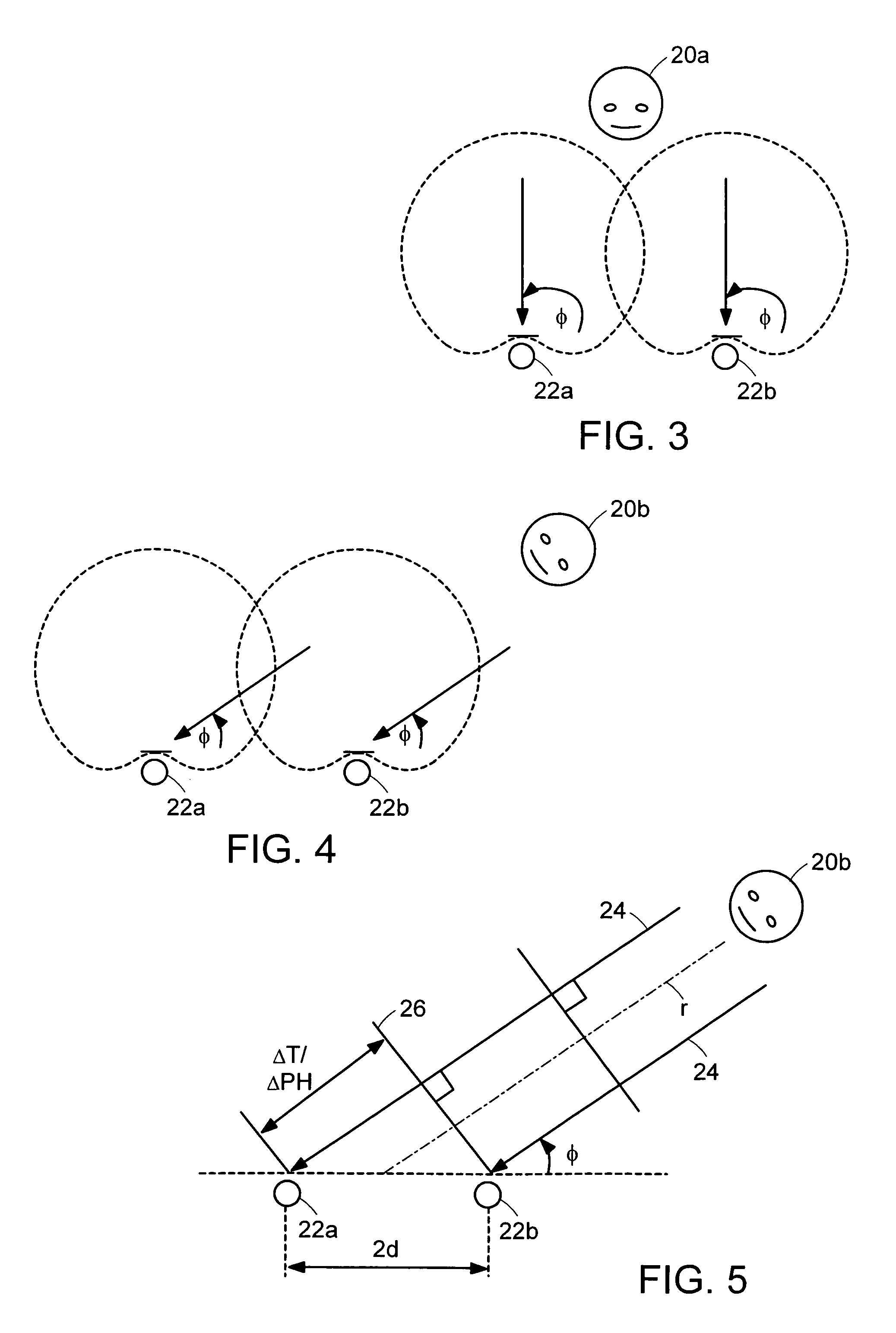
[0032]As used herein, the term “far field” generally refers to a microphone spaced and separated from an acoustic source by more than three inches. The term “microphone array” refers to two or more microphones placed along one axis or two axes a spaced and known distance apart. “Angle of incidence” or “angle of impingement,” refers to the angle at which the linear direction of an acoustic wave travels to and contacts the microphone array. For example, if an acoustic source emits an acoustic wave that travels to and contacts a plane in which the microphone array is arranged, and that angle of incidence is perpendicular to the plane, the angle of incidence is said to be at 0°. If the acoustic wavefront travels parallel to the plane or linear axis formed by the microphone array, then the angle of incidence is 90° positive or negative depending on the direction at which the wavefront travels.

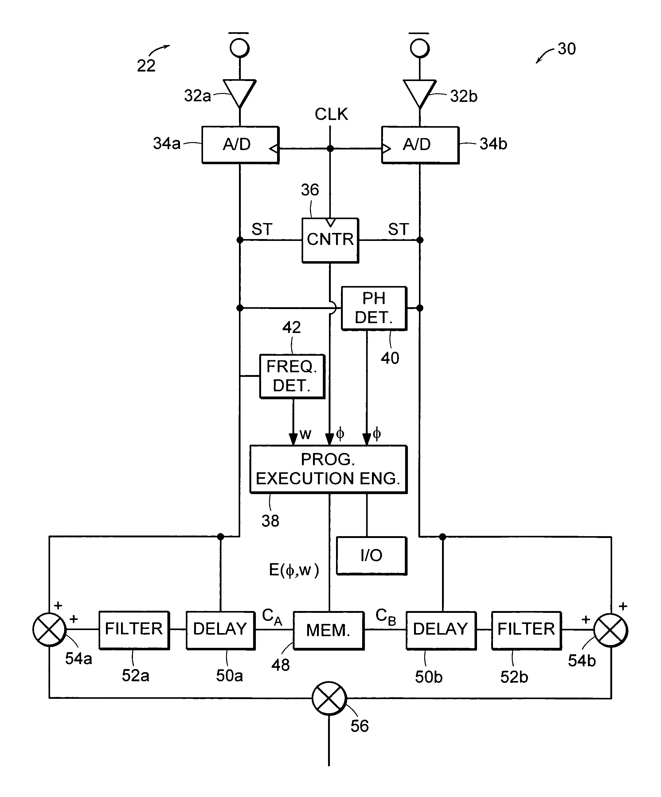
[0033]The microphone array can be embedded within a casing of a system, with the pressure-sensit...


PUM


Abstract

A system and method are provided for automatically tracking the movements of an acoustic source relative to two or more microphones possibly mounted in a portable device. The microphones are mounted so that they may be separated from an acoustic source that can be more than three inches from the portable device. By automatically tracking the location of a portable device, a directional response of unidirectional microphones in a far field setting can be steered so that the radial axis of the directional response aligns with the path in which the acoustic wave travels from the source to the microphones. By tracking the source and steering the directional response of the microphones, the system can thereby properly delay and filter electrical signals added to the outputs from corresponding microphones to maximize the signal-to-noise ratio of the ensuing signal.

Description

BACKGROUND OF THE INVENTION[0001]1. Field of the Invention[0002]The present invention relates in general to the field of microphones and tablet personal computers and, more particularly, to a plurality of microphones possibly arranged in the tablet (i.e., a microphone array) that has a directional polar response that continuously and automatically adapts to movement of an acoustic source.[0003]2. Description of the Related Art[0004]The following descriptions and examples are not admitted to be prior art by virtue of their inclusion within this section.[0005]A microphone is generally recognized as an electro-acoustic transducer that converts an acoustic or sonic wave into an electrical signal. There are numerous types of transducers on the market, including piezoelectric transducers or transducers having a diaphragm that is pressure-sensitive.[0006]Depending on the application, microphones can be chosen having different performance criteria. For example, a microphone can be embedded ...

Claims


Application Information

Patent Timeline
IPC IPC(8): H04R3/00
CPCG01S3/807G01S3/8083H04R1/406H04R3/005H04R2499/11H04S7/304
Inventor GRIFFIN, MICHAEL R.
Owner ZEBRA TECH CORP
Why Eureka
Try Eureka