Assembly comprised of a vane and of a cooling liner, turbomachine nozzle guide vanes assembly comprising this assembly, turbomachine and method of fitting and of repairing this assembly

a technology of cooling liner and assembly, which is applied in the direction of machines/engines, stators, liquid fuel engines, etc., can solve problems such as pressure drop

Active Publication Date: 2010-10-26
SN DETUDE & DE CONSTR DE MOTEURS DAVIATION S N E C M A
View PDF10 Cites 16 Cited by
  • Summary
  • Abstract
  • Description
  • Claims
  • Application Information

AI Technical Summary

Benefits of technology

[0013]In solving a specific problem, the Applicant Company also discovered that it was possible to considerably simplify the fitting of the assembly. Specifically, the presence of an insert near the flange has a highly effective effect on air leaks, which means that there is no longer any need to braze the flange to the nozzle guide vanes assembly perfectly. It is therefore possible simply to fix the liner to the vane by spot welding between the flange and the rim, leaks being avoided by virtue of the insert. The time and cost savings are considerable by comparison with brazing around the entire periphery of the flange.
[0030]Such a method has the advantage of the simplicity with which it can be implemented.

Problems solved by technology

Such an insert creates a pressure drop.
Specifically, since the flange is fixed, any air leaks there might be could leak only through a small clearance between the flange and the rim.

Method used


Image

  • Assembly comprised of a vane and of a cooling liner, turbomachine nozzle guide vanes assembly comprising this assembly, turbomachine and method of fitting and of repairing this assembly
  • Assembly comprised of a vane and of a cooling liner, turbomachine nozzle guide vanes assembly comprising this assembly, turbomachine and method of fitting and of repairing this assembly
  • Assembly comprised of a vane and of a cooling liner, turbomachine nozzle guide vanes assembly comprising this assembly, turbomachine and method of fitting and of repairing this assembly

Examples


first embodiment

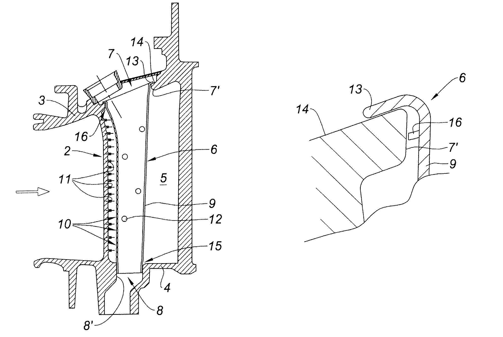
[0045]With reference to FIG. 3, the insert 16 comprises, a peripheral strip 16 or peripheral leaf fixed around the liner 6, under the flange 13. This metal strip 16 is designed to extend radially over a distance shorter than the distance separating the wall of the liner 6 from the wall 7′ of the outer opening 7 at this point, preferably lying flush with the latter. The expression “radially” is to be understood as meaning radially with respect to the overall axis of the liner, that is to say with respect to its longitudinal direction between the flange 13 and the end portion 15. The pressure drop thus created is enough to prevent or satisfactorily limit leaks between the flange 13 and the rim 14. In this embodiment, the insert forms a baffle, against air flow, around the entire periphery of the liner 6.

second embodiment

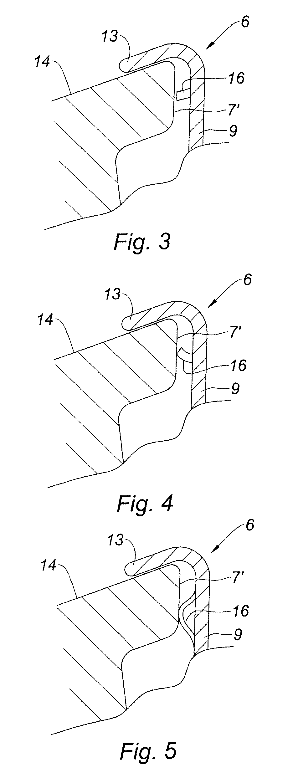
[0046]With reference to FIG. 4, the insert 16 comprises, a peripheral leaf 16 that exhibits a certain elasticity. This metal leaf 16 has a radial dimension which may perhaps be greater than the average distance separating the wall of the liner 6 from the wall 7′ of the outer opening 7 at this point. When the liner 6 is introduced into the opening 7, there is no harm in the liner 6 not being perfectly centered with respect to the opening 7. The leaf 16 bears against the wall portions 7′ of the opening 7 to which the liner 6 is closest and curves elastically outward as the liner 6 is introduced, thus compensating for the clearance. Provision may incidentally be made for the dimension of the leaf 16 to be such that the leaf comes into contact with the wall 7′ of the opening 7 over the entire periphery of the liner 6, thus forming a seal.

[0047]By virtue of this embodiment it is possible to leave a clearance between the liner 6 and the wall 7′ of the outer opening 7. Such a clearance ma...

third embodiment

[0049]With reference to FIG. 5, the insert 16 comprises, a peripheral spring 16. This spring 16, which is made of metal, comprises a leaf the edges of which are fixed to the surface of the liner 6, the leaf exhibiting a flared U-shaped cross section between the two fixed edges. As before, such a spring-forming element 16 is able to compensate for any clearance there might be at the outer opening 7 and may, depending on the region of the liner 6, act as a seal and / or as a baffle according to whether or not the spring 16 is in contact with the wall 7′ of the opening 7.

[0050]The insert has been presented according to three preferred embodiments but it goes without saying that it is possible to imagine other structures provided they extend between the wall of the liner 6 and that of the opening 7 to create a pressure drop. It is also possible to combine several inserts and create a kind of labyrinth seal.

[0051]By virtue of the insert 16, air leaks at the flange 13 are, if not completel...


PUM


Abstract

An assembly includes a vane and a cooling liner for cooling the vane, the vane having a central cavity with at least one first opening into which the liner extends, the liner having a flange fixed to the rim of the opening. This assembly includes, near the flange, a peripheral insert inserted between the wall of the liner and the wall of the opening.

Description

BACKGROUND OF THE INVENTION AND DESCRIPTION OF THE PRIOR ART[0001]The invention relates to an assembly comprised of a vane and of a cooling liner for cooling the vane, in a turbomachine nozzle guide vanes assembly.[0002]A turbomachine comprises rotor stages—compressor and / or turbine rotor stages—separated by nozzle guide vanes assemblies. The latter comprise a plurality of fixed vanes intended to guide the streams of gas. The fixed vanes extend, in the path of the gases, between an outer shroud and an inner shroud. Because of the temperature of the gases passing through them, particularly in the nozzle guide vanes assemblies separating turbine stages, the vanes are subjected to very severe operating conditions; it is therefore necessary to cool them, generally by forced convection or alternatively by the impact of air, within the vanes.[0003]For air impact cooling it is possible to use multiperforated longitudinal liners. These liners are generally made of a heat-resistant alloy, fo...

Claims


Application Information

Patent Timeline
Patent Type & Authority Patents(United States)
IPC IPC(8): F01D5/18
CPCF01D5/18F01D5/189F01D9/041F01D9/065F01D11/005F01D25/12F05D2260/607F05D2260/201
Inventor DERVAUX, ALEXANDRE NICOLASBAUMAS, OLIVIER JEAN DANIELBACHA, JEAN-LUC
Owner SN DETUDE & DE CONSTR DE MOTEURS DAVIATION S N E C M A
Why Eureka
Try Eureka