
System and method to identify and measure organ wall boundaries

a technology of organ wall and boundary, applied in the field of ultrasound-based diagnostic systems and procedures, can solve the problems of inaccurate border detection and prevent an accurate assessment of a true medical condition, and achieve the effect of accurate detection and delineation

Active Publication Date: 2010-10-26
VERATHON
View PDF245 Cites 24 Cited by
  • Summary
  • Abstract
  • Description
  • Claims
  • Application Information

AI Technical Summary

Benefits of technology

The patent describes ultrasound systems and methods that can create 2D and 3D images of a cavity structure within an organ or structure. These systems can accurately detect and outline the shape of the cavity by analyzing the surrounding tissue. The systems use different frequencies for probing the area and can even detect if the cavity is spherical or non-spherical. This technology can help improve the accuracy of ultrasound imaging and aid in the diagnosis and treatment of various medical conditions.

Problems solved by technology

However, inaccurate border detection, as shown in the inaccurately segmented bladder cavities of FIGS. 5 and 6 in which the bladder cavity border significantly overlaps into surrounding echogenic tissue to overestimate the bladder cavity size, or carves out a lumen area to underestimate the bladder size.
Thus a false internal boundary is presented and prevents an accurate assessment of a true medical condition since the bladder cavity area and volume is either underestimated or overestimated.

Method used


Image

  • System and method to identify and measure organ wall boundaries
  • System and method to identify and measure organ wall boundaries
  • System and method to identify and measure organ wall boundaries

Examples


Embodiment Construction

[0017]Ultrasound systems and methods to dynamically develop and present 2D and 3D images of a cavity structure within a region-of-interest (ROI) that is either partially or completely surrounded by echogenic tissue to permit the accurate detection and delineation of close contours of a cavity-tissue interface in the wall region of an organ or structure. The ultrasound systems and algorithmic methods are adapted to detect and segment cavities according to the shape of the cavity and the degree to which the cavity is surrounded by higher echogenic tissue by dynamically analyzing pixel groups near the cavity-tissue interface. The transceivers used by the ultrasound systems vary in the fundamental frequency used for probing the ROI. The algorithms vary as to which fundamental or harmonic frequency is used for imaging and whether the cavity is substantially spherical or substantially non-spherical.

BRIEF DESCRIPTION OF THE DRAWINGS

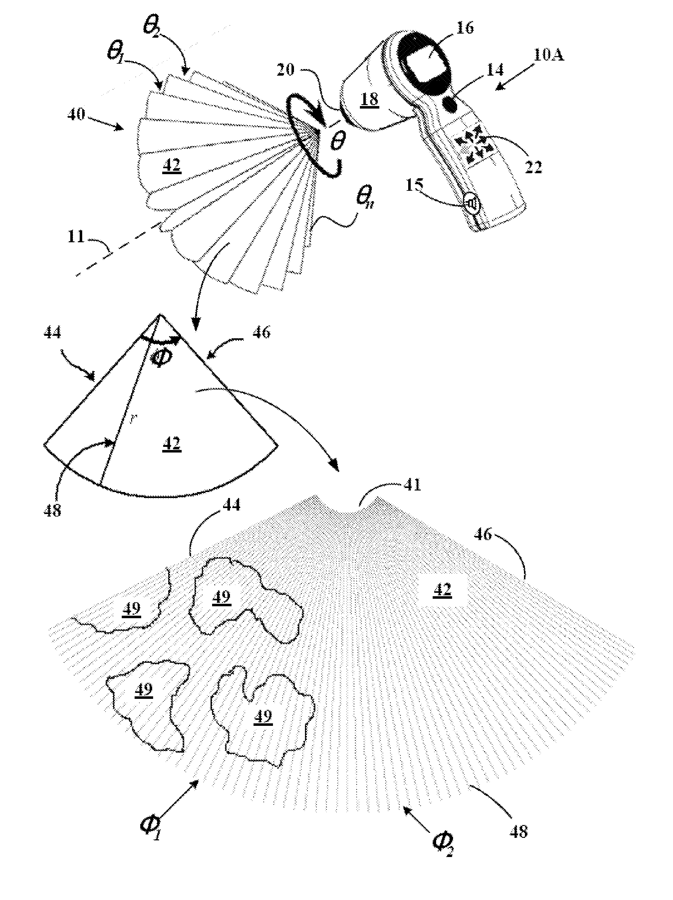
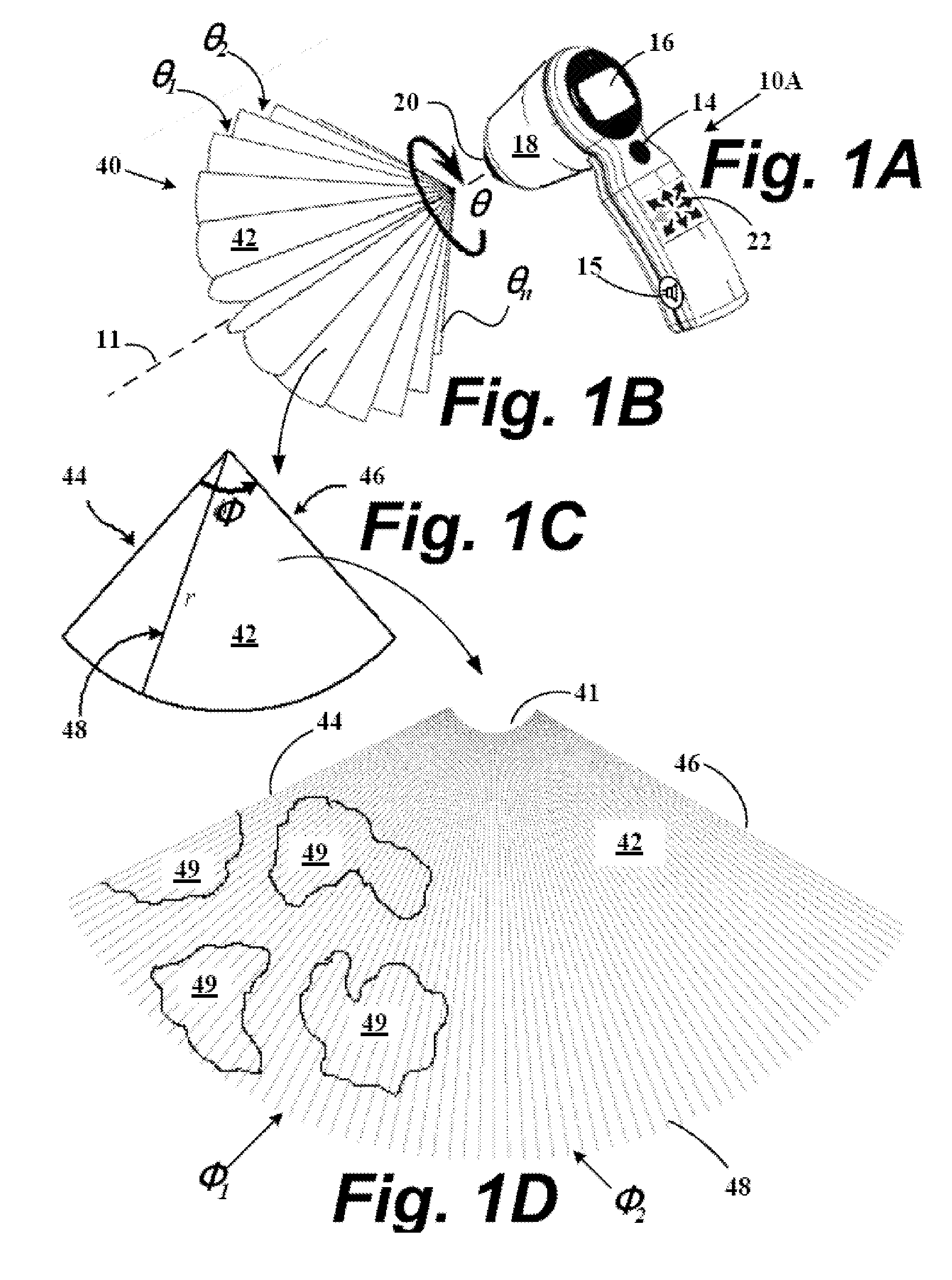
[0018]FIGS. 1A-D depicts a partial schematic and a partial...


PUM


Abstract

Systems and methods are described for acquiring, processing, and presenting boundaries of a cavity-tissue interface within a region-of-interest in an ultrasound image based upon the strength of signals of ultrasound echoes returning from structures within the region-of-interest. The segmentation of boundaries of cavity shapes occupying the region-of-interest utilizes cost function analysis of pixel sets occupying the cavity-tissue interface. The segmented shapes are further image processed to determine areas and volumes of the organ or structure containing the cavity within the region-of-interest.

Description

RELATED APPLICATIONS[0001]This application incorporates by reference and claims priority to U.S. provisional patent application Ser. No. 60 / 882,888 filed Dec. 29, 2006.[0002]This application incorporates by reference and claims priority to U.S. provisional patent application Ser. No. 60 / 828,614 filed Oct. 6, 2006.[0003]This application incorporates by reference and claims priority to U.S. provisional patent application Ser. No. 60 / 760,677 filed Jan. 20, 2006.[0004]This application is a continuation-in-part of and claims priority to U.S. patent application Ser. No. 11 / 213,284 filed Aug. 26, 2005.[0005]This application claims priority to and is a continuation-in-part of U.S. patent application Ser. No. 11 / 119,355 filed Apr. 29, 2005, now U.S. Pat. No. 7,520,857, which claims priority to U.S. provisional patent application Ser. No. 60 / 566,127 filed Apr. 30, 2004. This application also claims priority to and is a continuation-in-part of U.S. patent application Ser. No. 10 / 701,955 filed ...

Claims


Application Information

Patent Timeline
Patent Type & Authority Patents(United States)
IPC IPC(8): A61B8/00
CPCA61B5/1075A61B8/08A61B8/0858A61B8/4455A61B8/4483A61B8/467A61B8/483G06T7/0012G06T7/0083G06T7/0089A61B5/204G06T2207/30004A61B5/418A61B5/7264A61B8/565G06T2207/10132G06T2207/20101G06T2207/20116G06T2207/20161A61B8/4427A61B8/4472A61B8/461A61B8/469G06T7/12G06T7/149
Inventor YANG, FUXINGDUDYCHA, STEPHENMCMORROW, GERALD
Owner VERATHON
Learn More