Ultrasound system and method for measuring bladder wall thickness and mass

a technology of ultrasound imaging and measurement of bladder wall thickness, applied in the field of ultrasound imaging systems and methods, can solve the problems of unsatisfactory hypertrophy of bladder muscle, renal failure, patient death, etc., and achieve the effect of improving accuracy and precision of wall location loci

Inactive Publication Date: 2010-02-11
VERATHON
View PDF102 Cites 30 Cited by
  • Summary
  • Abstract
  • Description
  • Claims
  • Application Information

AI Technical Summary

Benefits of technology

[0021]The collection of two-dimensional and one-dimensional algorithms includes ultrasound B-mode based segmentation and specialized snake algorithms to determine the surface area of the organ wall and to provide an initial front wall location. The initial front wall location determined by the B-mode algorithms is sufficiently precise to be further processed by the one-dimensional algorithms. The one-dimensional algorithms are unique sequences of A-mode based algorithms applied to the echogenic ultrasound scanlines to further improve the accuracy and precision of wall location loci as initially determined by the B-mode algorithms.

Problems solved by technology

Accordingly, an undesired hypertrophy of the bladder muscle often results.
As the bladder volume increases in response to increased internal bladder pressure, the bladder walls elongate and decrease in thickness, resulting in the distention.
When hyperdistension occurs, the bladder fills with an excessive amount urine and generates an internal bladder pressure that may cause serious adverse effects, including renal damage, renal failure, or even death of the patient from autonomic dysreflexia if the patient has spinal cord damage.
At low bladder volumes, bladder distension information is not typically useful since normal humans have widely varying bladder capacities.
Thus, it is more difficult to establish a volume threshold at which over-distension occurs or when incontinence occurs for a selected individual.
Unfortunately, the application of these current methods to determine bladder wall thickness are susceptible to operator error, are time consuming, and generally lead to inaccurate estimations of the bladder wall thickness.
Since the operator must repeatedly reposition the ultrasound probe until a bladder wall image is sufficiently visible, inaccuracies may be introduced into the ultrasound data.
Consequently, current ultrasound methods to determine bladder wall thickness is an unreliable or ineffective means to measure bladder distension.

Method used


Image

  • Ultrasound system and method for measuring bladder wall thickness and mass
  • Ultrasound system and method for measuring bladder wall thickness and mass
  • Ultrasound system and method for measuring bladder wall thickness and mass

Examples


Embodiment Construction

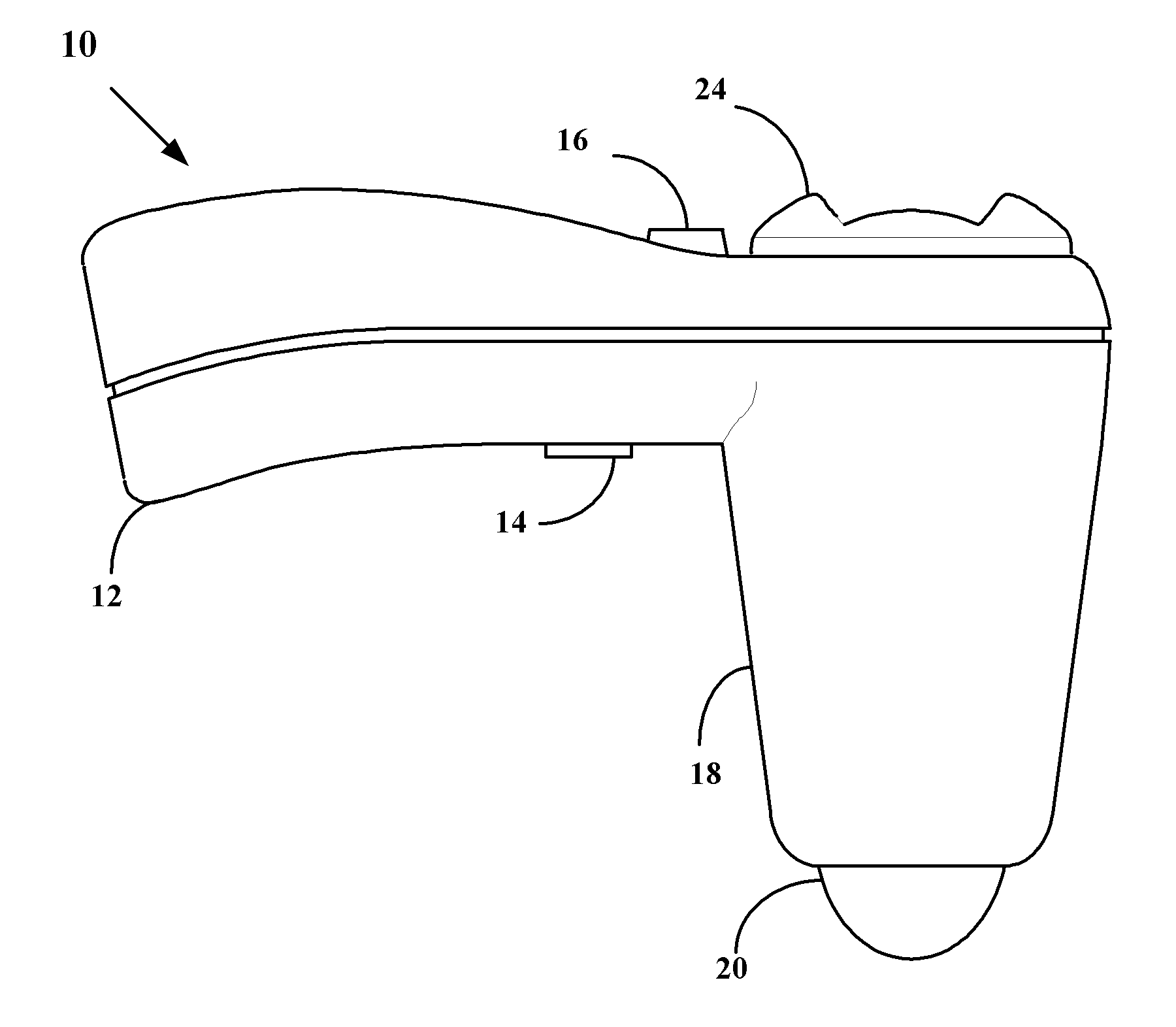
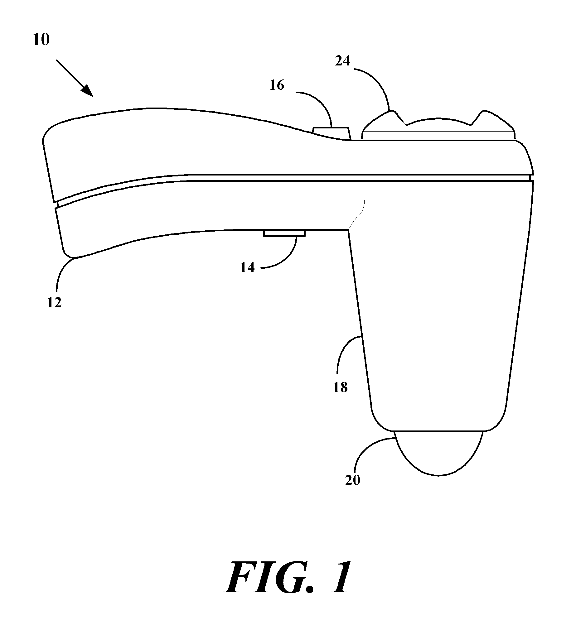
[0089]FIG. 1 is a side elevational view of an ultrasound transceiver 10. Transceiver 10 includes a transceiver housing 18 having an outwardly extending handle 12 suitably configured to allow a user to manipulate transceiver 10. The handle 12 includes a trigger 14 that allows the user to initiate an ultrasound scan of a selected anatomical portion, and a cavity selector 16, described below. Transceiver 10 includes a transceiver dome 20 that contacts a surface portion of the patient when the selected anatomical portion is scanned to provide an appropriate acoustical impedance match and to properly focus ultrasound energy as it is projected into the anatomical portion. The transceiver 10 further includes an array of separately excitable ultrasound transducer elements (not shown in FIG. 1) positioned within the housing 18. The transducer elements are suitably positioned within the housing 18 to project ultrasound energy outwardly from the dome 20, and to permit reception of acoustic ref...


PUM


Abstract

An ultrasound transceiver scans an organ and processes the echogenic signals to produce three-dimensional, two-dimensional, and one-dimensional information of the organ. The 3-D, 2-D, and 1-D information is utilized to determine the thickness, surface area, volume, and mass of the organ wall.

Description

PRIORITY CLAIM[0001]This application claims priority to U.S. patent application Ser. No. 11 / 061,867 filed Feb. 17, 2005.[0002]This application claims priority to U.S. Provisional Patent Application Ser. No. 60 / 566,823, filed Apr. 30, 2004; to U.S. Provisional Patent Application Ser. No. 60 / 566,818, filed Apr. 30, 2004; and to U.S. Provisional Patent Application Ser. No. 60 / 545,576, filed Feb. 17, 2004. This application claims priority to U.S. patent application Ser. No. 11 / 064,114 filed Feb. 17, 2005.[0003]This application also claims priority to U.S. application Ser. No. 11 / 010,539 filed Dec. 13, 2004, which claims priority to PCT / EP03 / 07807 filed Jul. 17, 2003, which claims priority to UK Application Serial No. 0218547.8 filed Aug. 9, 2002; and U.S. patent application Ser. No. 10 / 704,996, filed Feb. 3, 2005, which claims priority to PCT / EP03 / 07807 filed Jul. 17, 2003, which claims priority to UK Application Serial No. 0218547.8 filed Aug. 9, 2002.[0004]This application is also a c...

Claims


Application Information

Patent Timeline
Patent Type & Authority Applications(United States)
IPC IPC(8): A61B8/00
CPCA61B8/0858A61B8/483G01S7/52036G01S7/52053G01S7/52074G06T2207/30004G01S15/8909G06T7/602G06T2207/10136G06T2207/20148G01S7/52085G06T7/136G06T7/62
Inventor CHALANA, VIKRAMDUDYCHA, STEPHENMCMORROW, GERALDYUK, JONGTAESHELTON, TIMBARNARD, BILL
Owner VERATHON
Why Eureka
Try Eureka