Ripple reduction for switch-mode power conversion

a power converter and switch-mode technology, applied in the field of switch-mode power converters, can solve the problems of significant challenges, inability to meet the needs of more challenging applications, and inability to sustain power losses in the windings, and achieve the effect of reducing the level of output ripple voltage, low output ripple voltage, and low output ripple voltag

Inactive Publication Date: 2010-10-26
JACOBS MARK E
View PDF8 Cites 7 Cited by
  • Summary
  • Abstract
  • Description
  • Claims
  • Application Information

AI Technical Summary

Benefits of technology

[0010]In an advantageous embodiment, the ac voltage produced by the inverter is substantially a rectangular waveform. In an advantageous embodiment, the magnetic circuit elements are inductors. In a further advantageous embodiment, the magnetic circuit elements are transformers. In an advantageous embodiment, the current-doubler rectification circuit includes a first diode and a second diode, each diode respectively coupled to a winding of one of the magnetic circuit elements and the output node. In an advantageous embodiment, the diodes are formed with active switches, commonly referred to as “synchronous rectifiers.” When the diodes are formed with active switches, a power flow between the input and the output may be reversed. In a further advantageous embodiment, the magnetic circuit elements are formed as an integrated magnetics structure. In a further advantageous embodiment, another magnetic circuit element is coupled to the voltage-sensing windings to reduce an effective number of turns therein.
[0012]A current-doubler rectification circuit, advantageously formed according to the principles of the invention, includes magnetic circuit elements contained therein adapted to a characteristic of the ac voltage source to produce a low level of output ripple voltage at a preselected duty cycle of the ac voltage source. The magnetic circuit elements can produce a low level of output ripple voltage at a preselected duty cycle by matching roughly an increasing slope of current in one magnetic circuit element with a decreasing slope of current in the other. The current-doubler rectification circuit further reduces the level of output ripple voltage by sensing a scaled voltage difference of voltages produced in the magnetic circuit elements, and producing therefrom a ripple-cancellation current that advantageously matches the error in the current slopes, and which is injected with the proper polarity into the output to cancel remaining ripple components.

Problems solved by technology

However, more recent designs of power converters frequently employ a “switch-mode” circuit topology in place of a less efficient dissipative regulator.
However, ripple components are produced at an input and an output of the power converter by the switching action of the power switch, which requires inclusion of a filter for their attenuation.
But inductors and other magnetic circuit elements are generally formed with multiple layers of copper windings wound around dissipative core materials such as soft ferrites, and sustain power losses in the windings due to skin and proximity effects.
Nonetheless, a significant challenge remains for a circuit designer to find a suitable design strategy for a magnetic circuit element with sufficiently low power dissipation characteristics for the more difficult applications.
Thus, despite the use of switch-mode power conversion circuit topologies and careful design of components used therein, market needs for the more challenging applications require further increases in the efficiency of a power converter beyond those presently being achieved.

Method used


Image

  • Ripple reduction for switch-mode power conversion
  • Ripple reduction for switch-mode power conversion
  • Ripple reduction for switch-mode power conversion

Examples


Embodiment Construction

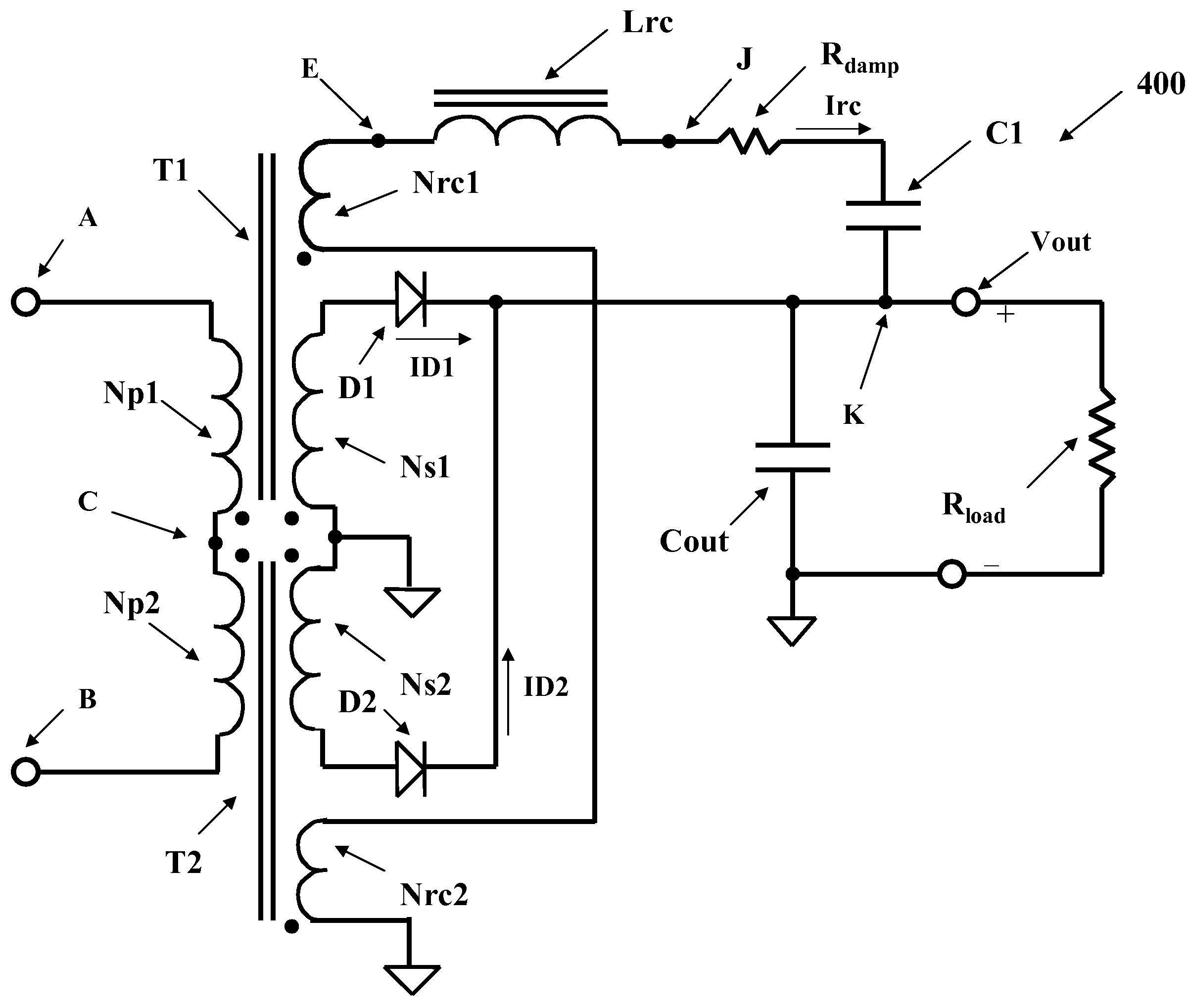
[0026]The specific embodiments of the invention discussed hereinbelow provide particular ways of implementing the invention, and are not provided to limit the scope thereof, or the context in which they are applied. The invention will be described with respect to preferred embodiments employing various switch-mode power conversion topologies that may benefit from a circuit to cancel or reduce a ripple current at an output thereof. The principles of the invention, however, may be applied to other types of power converters including, without limitation, motor controllers, power amplifiers, and other applications wherein a switch-mode power conversion circuit may be used to convert an input voltage waveform into an output voltage waveform. The language “switch-mode power conversion” as used herein includes power converter circuits including diodes passively coupled to an ac voltage source to produce a rectified output voltage.

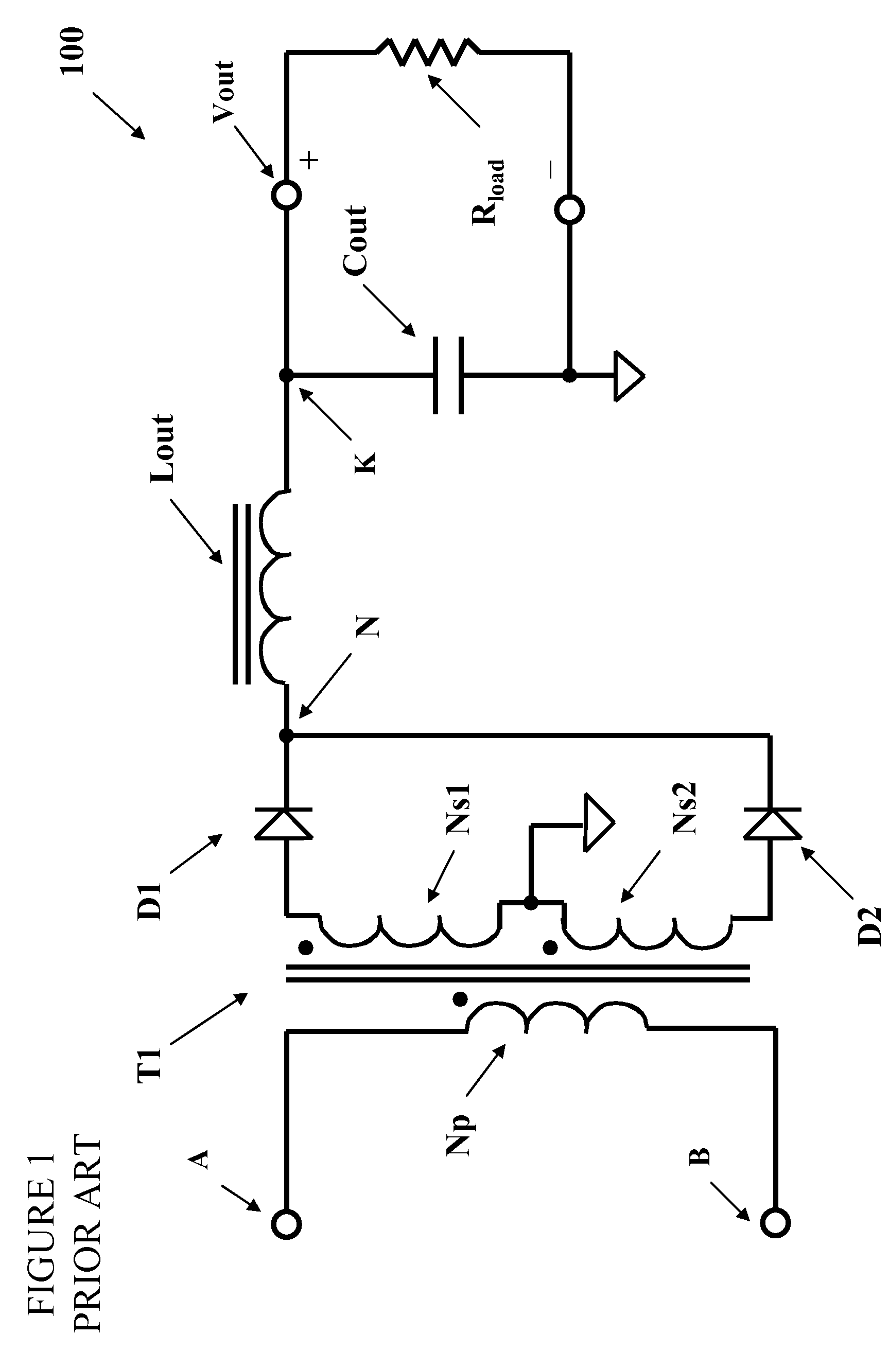
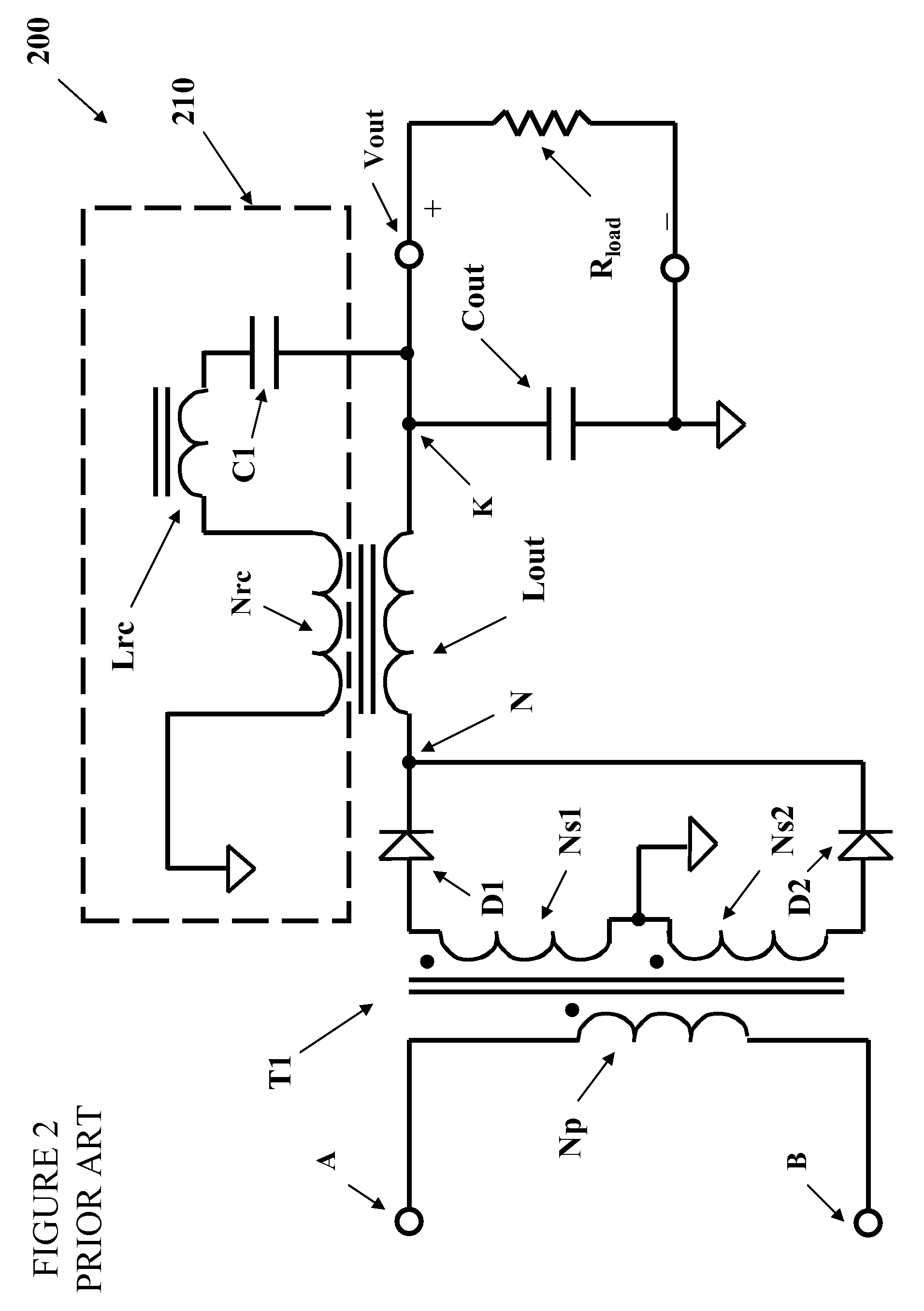
[0027]A current-doubler rectification circuit is described t...


PUM


Abstract

A power converter includes an isolated or a nonisolated current-doubler rectification circuit including two magnetic circuit elements, each magnetic circuit element formed with a primary winding and a voltage-sensing winding. The primary windings are coupled in series. The voltage-sensing windings are also coupled in series but with a coupling sense opposite from that of the primary windings. A properly sized inductor and capacitor are coupled in series with the voltage-sensing windings to produce a ripple-cancellation current with slope opposite to a net slope error of currents produced in the two magnetic circuit elements. The current-doubler rectification circuit is preferably coupled to a rectangular ac input waveform. By sensing a scaled voltage difference between two magnetic circuit elements, a very low level of output ripple is produced by the circuit with very low power losses over a range of operating conditions.

Description

[0001]This application claims the benefit of U.S. Provisional Application No. 60 / 863,440, entitled “Ripple Reduction for Switch-Mode Power Conversion,” filed on Oct. 30, 2006, which is incorporated herein by reference.TECHNICAL FIELD OF THE INVENTION[0002]The invention is directed in general to power converters and, more specifically, to a switch-mode power converter with reduced ripple at an output thereof.BACKGROUND[0003]A power converter is a power supply or power processing circuit that converts an input voltage waveform into an output voltage waveform. Important characteristics of power converters are the ability to regulate accurately a characteristic of the output voltage waveform such as a dc voltage level, the ability to produce the output voltage waveform with a low level of ripple voltage, and the ability to execute the power conversion process with high efficiency. Power conversion efficiency is the ratio of power converter output power to input power.[0004]Early designs...

Claims


Application Information

Patent Timeline
Patent Type & Authority Patents(United States)
IPC IPC(8): H02M1/14
CPCH02M1/14H02M7/06
Inventor JACOBS, MARK E.
Owner JACOBS MARK E
Why Eureka
Try Eureka