
Image forming apparatus with charge member and image supporting member having specific characteristics

a charge member and image support technology, applied in the field of image forming apparatus, can solve the problems of smearing the photosensitive drum, the wear of the photosensitive drum, the inability to charge the photosensitive drum uniformly, etc., and achieve the effect of preventing an image d

Inactive Publication Date: 2010-10-26
OKI DATA CORP
View PDF12 Cites 0 Cited by
  • Summary
  • Abstract
  • Description
  • Claims
  • Application Information

AI Technical Summary

Benefits of technology

"The present invention relates to an image forming apparatus that can prevent image defects caused by charges with polarity opposite to that of the charge voltage. The apparatus includes an image supporting member, a charge member, an exposure member, a developer supporting member, and a transfer member. The image supporting member has a dark decay characteristic ratio of 95% or less relative to charges with polarity opposite to that of the charge voltage. The charge member charges the surface of the image supporting member, the exposure member forms a latent image on the charged surface, the developer supporting member develops the latent image to form a toner image, and the transfer member transfers the toner image to a medium. The image supporting member has a specific relationship between its surface potential and the transfer current. This configuration ensures that image defects caused by charges with polarity opposite to that of the charge voltage are prevented."

Problems solved by technology

In the conventional image forming apparatus described above, when images are formed or a printing operation is performed continuously, each of the components such as the photosensitive drum, the charging roller, and the cleaning roller tends to wear.
As a result, the ingredient may stick to a surface of the photosensitive drum, thereby smearing the photosensitive drum.
However, in the conventional printer, when the plastic film is removed, the plastic film is pulled against friction between the photosensitive drum and the charging roller or the developing roller.
If the generated charge remains on the photosensitive drum, it is difficult to charge the photosensitive drum uniformly due to the generated charge when the charge roller charges the photosensitive drum.
As a result, an image defect such as a dark spot and a streak may occur upon printing, thereby deteriorating image quality.
Further, if static discharge occurs between the photosensitive drum and an external environment, a toner image tends to be distorted when the transfer roller applies a transfer voltage, thereby deteriorating image quality.

Method used


Image

  • Image forming apparatus with charge member and image supporting member having specific characteristics
  • Image forming apparatus with charge member and image supporting member having specific characteristics
  • Image forming apparatus with charge member and image supporting member having specific characteristics

Examples


first embodiment

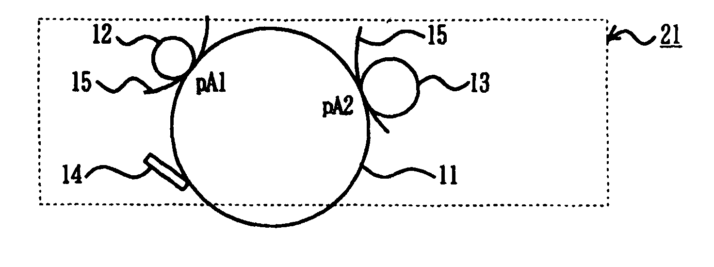
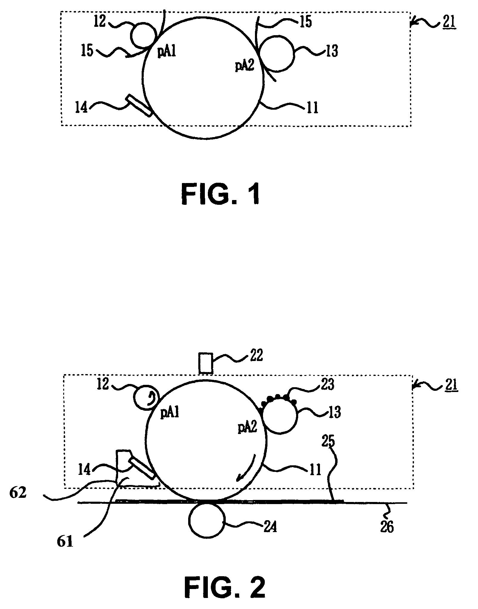
[0027]FIG. 1 is a schematic view showing an image drum cartridge in a stored state according to a first embodiment of the present invention. FIG. 2 is a schematic view showing a printer according to the first embodiment of the present invention. As shown in FIG. 1, a photosensitive drum or an image supporting member 11 is provided with a photosensitive layer on a conductive supporting body. A charge roller 12 is a roller member formed of a conductive rubber. The charge roller 12 is disposed to be rotatable while contacting with the photosensitive drum 11 at a contact point pA1.

[0028]A developing roller or developer supporting member 13 is a roller member formed of a conductive rubber. The developing roller 13 is disposed to be rotatable while contacting with the photosensitive drum 11 at a contact point pA2. A cleaning blade 14 is formed of a rubber plate, and is arranged to contact with the photosensitive drum 11 at a tip thereof. A cleaning device 62 is formed of the cleaning blad...

example 1

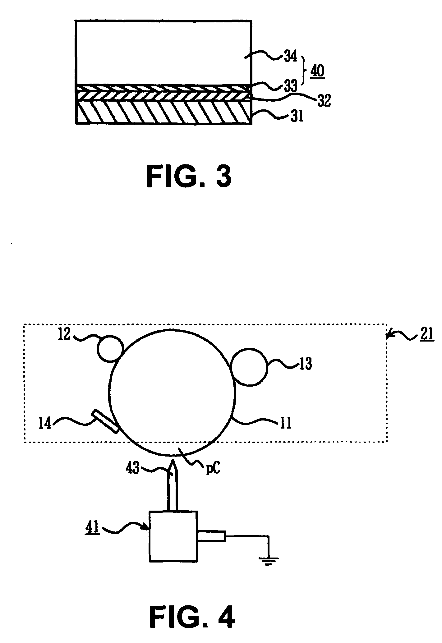
[0041]In Example 1, the conductive supporting member 31 is formed of an aluminum alloy cylinder having a polished mirror surface, and has an outer diameter of 30 mm, a length of 351 mm, and a thickness of 1.0 mm. The blocking layer 32 of an anodic oxide coating (alumite coating) with a thickness of about 6.0 μm is formed on a surface of the conductive supporting member 31. The surface of the conductive supporting member 31 is treated with an anodic oxide coating process followed by sealing with nickel acetate to form the anodic oxide coating (alumite coating).

[0042]A process of forming the charge generating layer 33 is as follows. First, 10 weight parts of a charge generating material of a phthalocyanine type is added to 150 weight parts of 1,2-dimethoxy ethane. The mixture is treated through a milling-dispersion process with a sand mill, thereby obtaining a pigment dispersion. The conductive supporting member 31 with the blocking layer 32 is immersed in the pigment dispersion or a ...

example 2

[0044]In example 2, the photosensitive drum 11 is manufactured through a process similar to that of example 1, except that 0.2 weight parts of an electron-attracting compound is added in the charge transporting layer 34. The electron-attracting compound prevents remaining charges from forming in the charge transporting layer 34. In example 2, the electron-attracting compound is represented by the following chemical formula.

[0045]


PUM


Abstract

An image forming apparatus includes: an image supporting member; a charge member for charging a surface of the image supporting member; an exposure member for forming a latent image on the surface of the image supporting member charged by the charge roller; a developer supporting member for developing the latent image formed by the exposure member to form a toner image; and a transfer member for transferring the toner image formed by the developer supporting member to a medium. The image supporting member has a dark decay characteristic ratio of 95% or less relative to charges having a polarity opposite to that of a charge voltage applied by the charge member.

Description

BACKGROUND OF THE INVENTION AND RELATED ART STATEMENT[0001]The present invention relates to an image forming apparatus.[0002]In a conventional image forming apparatus such as a printer, a copier, and a facsimile, an image is formed through the following process. First, a charge roller charges a surface of a photosensitive drum. An exposure device such as an LED head exposes the surface of the photosensitive drum to form a static latent image or a latent image thereon. A developing roller attaches a thin layer of toner to the static latent image to form a toner image. A transfer roller transfers the toner image to a recording medium, thereby forming an image. A cleaning device removes toner remaining on the photosensitive drum after the transfer roller transfers the toner image.[0003]In the conventional image forming apparatus described above, when images are formed or a printing operation is performed continuously, each of the components such as the photosensitive drum, the charging...

Claims


Application Information

Patent Timeline
Patent Type & Authority Patents(United States)
IPC IPC(8): G03G15/045
CPCG03G5/047G03G21/06G03G2215/1614
Inventor MOTOMURA, MIKIO
Owner OKI DATA CORP
Learn More