Liquid manure applicator, method, and tool with bellows type downforce system

a technology of liquid manure and downforce system, which is applied in the field of farming practice, can solve the problems of increasing the cost of raising the crop to which the fertilizer is applied, generating significant amounts of waste, and high cost of alternative chemical or petrochemical based fertilizers, and achieves the effect of increasing or decreasing the air pressure inside the bellows and reducing the force on the arm

Active Publication Date: 2010-11-02
ENVIRONMENTAL TILLAGE SYST
View PDF7 Cites 16 Cited by
  • Summary
  • Abstract
  • Description
  • Claims
  • Application Information

AI Technical Summary

Benefits of technology

[0015]Another aspect of this invention relates to a method for applying liquid manure to a farm field that has a plurality of laterally spaced, parallel zones in which crops will be planted. The method comprises providing a supply of liquid manure which includes suspended solids therein, pumping the liquid manure to and through a distributor and through a plurality of distribution hoses that lead from the distributor, arranging outlet ends of the distributor hoses over the tilled zones such that the liquid manure is discharged atop the tilled zones, and restricting the size of the suspended solids that may pass from the distributor to the distribution hoses to a size that is substantially equal to or less than 50% of a cross-sectional area of the hoses.
[0016]Yet another aspect of this invention relates to a tool used in zone tillage farming in which a plurality of laterally spaced, parallel zones are provided in which row crops are planted. The tool comprises a tool frame. A pivotal arm is connected to the tool frame for pivoting about a first pivot axis. The arm carries at least one rotatable ground engaging member for rolling on the ground with the arm pivoting upwardly and downwardly in response to changes in ground contour. A device is mounted on the arm for performing an agricultural operation in one of the zones in the farm field. An expandable bellows puts a downforce on the arm that increases or decreases as air pressure inside the bellows is increased or decreased. The bellows is sandwiched and constrained between a pair of support surfaces with a first support surface being fixed to the arm and a second support surface being pivotal relative to the tool frame to be able to pivot with respect to the arm. A linkage operatively connects the second support surface to the arm such that pivoting motion of the arm also pivots the second support surface such that the second support surface remains substantially parallel to the first support surface to avoid uneven motion of opposite sides of the bellows as the arm pivots on the tool frame to follow ground contours.

Problems solved by technology

Many animal raising operations, such as large scale, modern hog farms and the like, have large numbers of animals that generate significant amounts of waste.
First, the cost of alternative chemical or petrochemical based fertilizers is very high and adds to the cost of raising the crop to which the fertilizer is applied.
Secondly, for a farmer who owns animals that generate large amounts of liquid manure, the farmer must find a way to dispose of the liquid manure.
It cannot be allowed to build up indefinitely.
Unfortunately, applying liquid manure to farm fields can be a difficult thing to do.
However, such filters are not completely effective in removing the suspended solids.
This means that the farmer has to remove the plug.
This is a dirty, time consuming and inconvenient task.
Such large hoses mean that large amounts of liquid manure will be pumped through the hoses and reach a certain area of ground as the distribution vehicle moves over the field.
This is a waste of liquid manure as it need not be applied to the field in such large quantities, particularly when one considers zone tillage.

Method used


Image

  • Liquid manure applicator, method, and tool with bellows type downforce system
  • Liquid manure applicator, method, and tool with bellows type downforce system
  • Liquid manure applicator, method, and tool with bellows type downforce system

Examples


Embodiment Construction

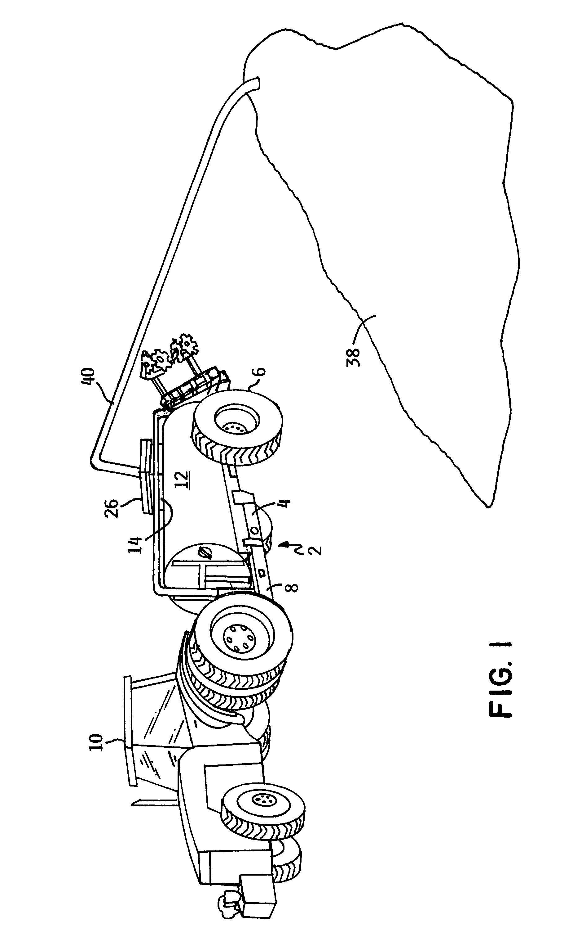
[0036]One embodiment of a liquid manure applicator according to this invention is generally illustrated as 2 in FIG. 1. Applicator 2 comprises a towed trailer 4 having a pair of rear ground engaging wheels 6. Trailer 4 includes a hitch 8 for coupling trailer 4 to a towing vehicle 10, such as a tractor. While applicator 2 is preferably in the form of a towed trailer 4, this need not necessarily be the case. Applicator 2 could also comprise a self-propelled vehicle.

The Tank and Inlet

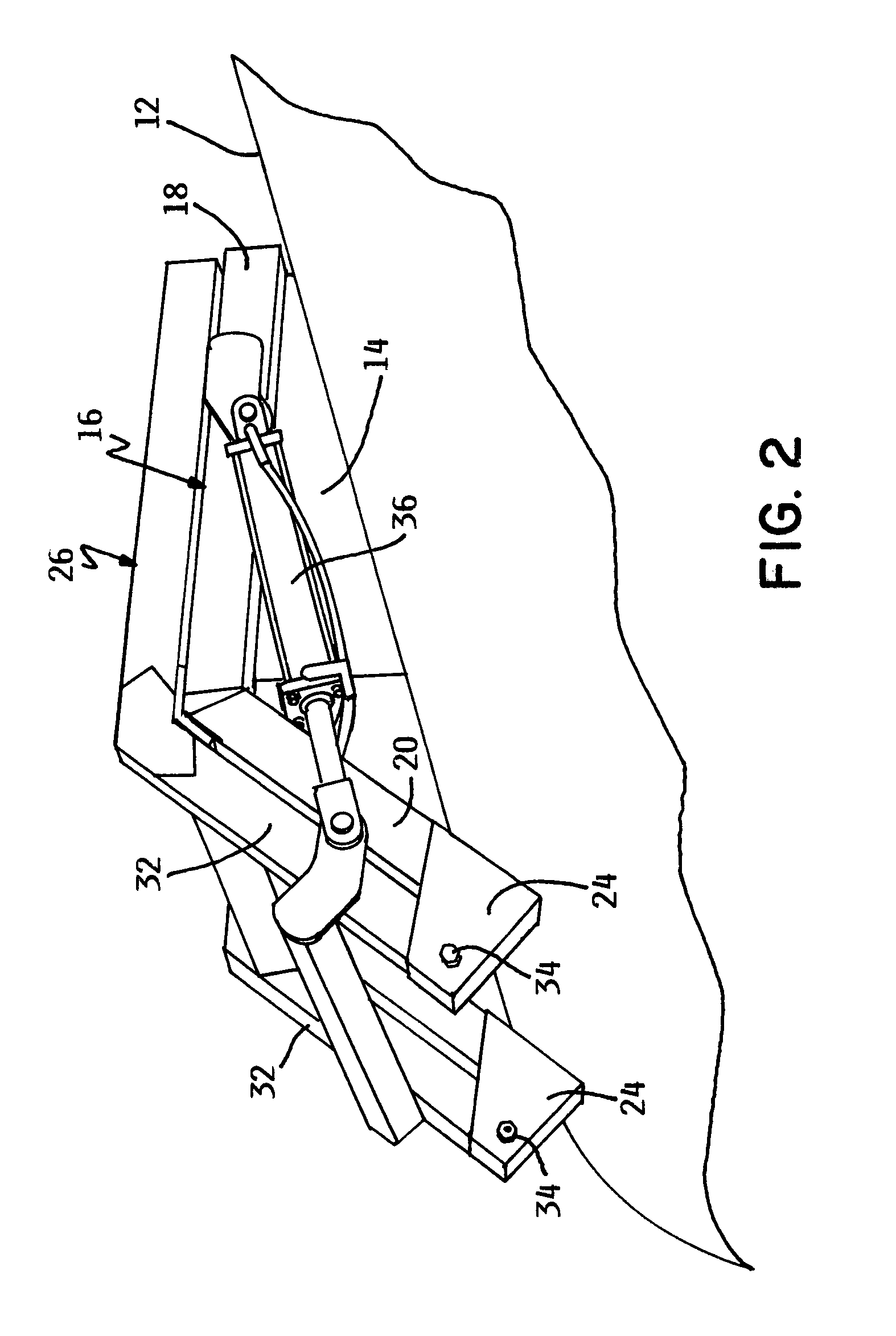
[0037]Applicator 2 includes a liquid manure storage tank 12 that extends substantially the full length of trailer 4. Referring to FIGS. 2 and 3, tank 12 includes an inlet 14 on a top wall of tank 12. Inlet 14 has an open, upwardly facing mouth 16 bounded by various beams 18. A pair of inclined supports 20 extend downwardly from beams 18 with each support 20 terminating in an upwardly extending foot 24 that abuts against the upper side of tank 12. Inlet 14 along with its open mouth 16 communicates to the in...


PUM


Abstract

A liquid manure applicator comprises a tank for holding a supply of liquid manure that is distributed onto a farm field through a distributor having a plurality of distribution ports and hoses. The hoses lead to individual distribution tools that include a pair or rotary coulters and a bellows for applying downforce to the coulters. The distributor includes a ring that restricts the size of the solids entering the distribution ports and hoses to something substantially equal to or less than 50% of the cross-sectional area of the hoses. This prevents the hoses from plugging even when small diameter hoses are used to lower the application rates to values more consistent with the needs of a zone tilled field. A rotary chopper in the distributor reduces the size of larger solids until they have been broken up into pieces small enough to pass the restriction provided by the ring.

Description

CROSS REFERENCE TO RELATED APPLICATIONS[0001]This application claims the benefit of one or more previously filed copending provisional applications identified as follows: Application Ser. No. 60 / 818,887 filed Jul. 6, 2006.TECHNICAL FIELD[0002]This invention relates generally to a farming practice involving the application of liquid manure to a farm field to fertilize the field using the manure. More particularly, this invention relates to a new method and applicator for applying liquid manure to farm fields that have been tilled using zone tillage. In addition, this invention relates to a tool and a system for applying downforce on the tool used either as part of the manure applicator or for zone tillage.BACKGROUND OF THE INVENTION[0003]Zone tillage is an environmentally friendly farming practice used in conjunction with the planting and growing of row crops, such as corn and soybeans. In zone tillage, only narrow strips or zones corresponding to the location of the crop rows that w...

Claims


Application Information

Patent Timeline
Patent Type & Authority Patents(United States)
IPC IPC(8): B05B1/20A01C17/00A01C23/00F23D11/04A01G25/09
CPCA01C23/003A01C23/007A01C23/002Y02P60/21
Inventor BAUER, MARK A.
Owner ENVIRONMENTAL TILLAGE SYST
Why Eureka
Try Eureka