Tuned optical cavity magnetometer

a magnetometer and optical cavity technology, applied in the field of magnetometers, can solve the problems of expensive cryogenic cooling

Inactive Publication Date: 2010-11-02
NAT TECH & ENG SOLUTIONS OF SANDIA LLC
View PDF10 Cites 94 Cited by
  • Summary
  • Abstract
  • Description
  • Claims
  • Application Information

AI Technical Summary

Benefits of technology

[0007]The present invention relates to an apparatus for sensing a magnetic field (i.e. a magnetometer) which comprises an optical cavity formed by a grating and a mirror which are spaced about a vapor cell which contains an alkali metal vapor. The vapor cell can also contain a buffer gas which can include a noble gas and which can also include nitrogen. A pump laser beam is directed into the vapor cell to magnetically polarize the alkali metal vapor which can be heated to a temperature which is effective to provide a density of the alkali metal vapor which is greater than 1011 atoms-cm−3 and which can range up to about 1015 cm−3.

Problems solved by technology

Conventional superconducting magnetometers based on superconducting quantum interference devices (SQUIDs) provide a high sensitivity for magnetic field detection but are bulky and require expensive cryogenic cooling.

Method used


Image

  • Tuned optical cavity magnetometer
  • Tuned optical cavity magnetometer
  • Tuned optical cavity magnetometer

Examples


Embodiment Construction

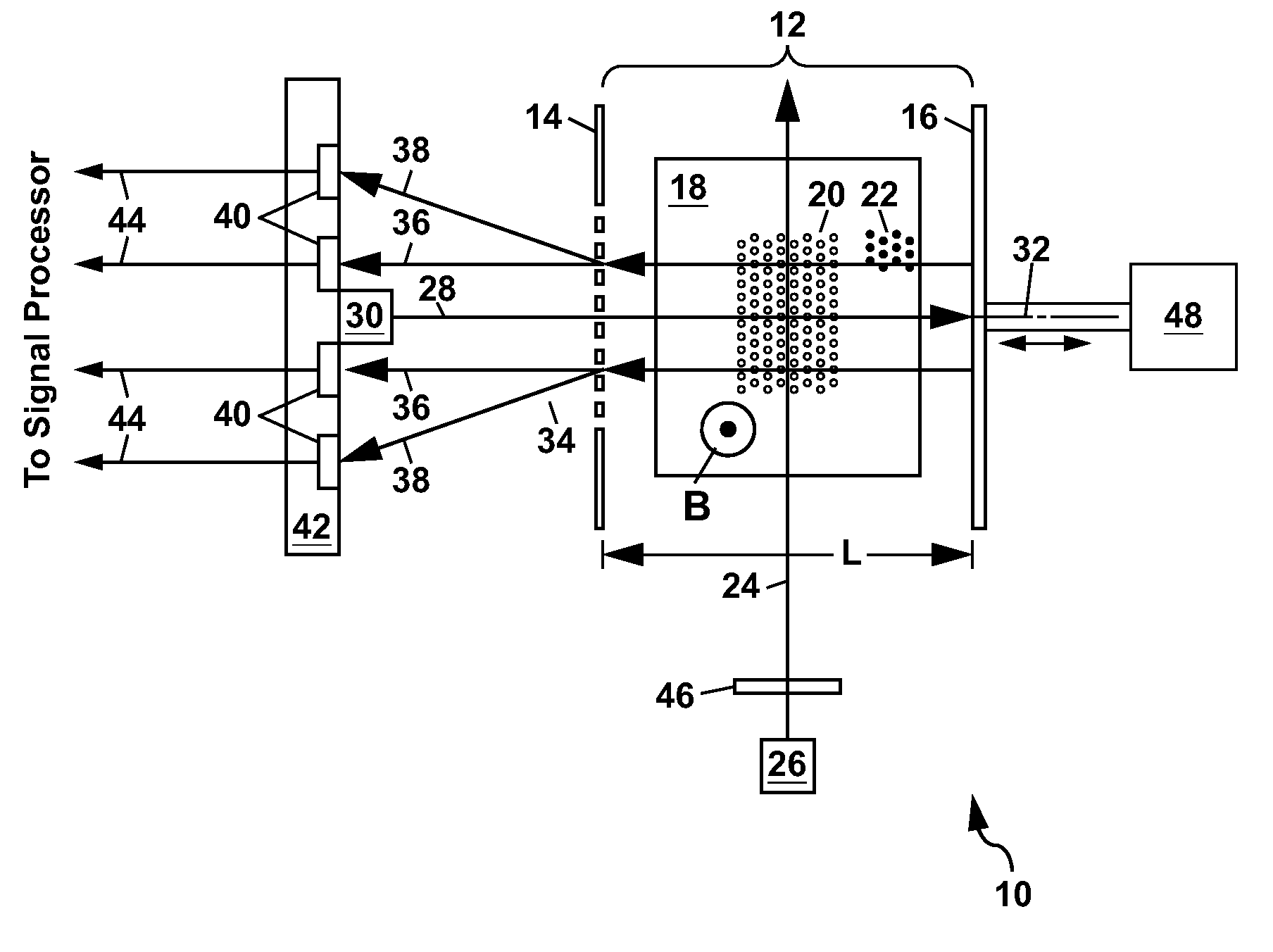
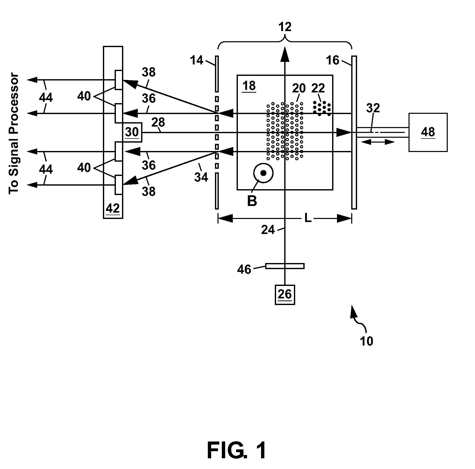
[0037]FIG. 1 shows a schematic diagram of a first example of an apparatus 10 for sensing a magnetic field according to the present invention. This apparatus 10, which is also referred to herein as a tunable optical cavity magnetometer 10 or simply as a magnetometer 10, comprises an optical cavity 12 which is formed by a grating 14 and a mirror 16, with a vapor cell 18 being located inside the optical cavity 12. The vapor cell 18 contains an alkali metal vapor 20 and can also contain a buffer gas 22 (e.g. comprising a noble gas such as neon). Another gas such as nitrogen can also be added to the buffer gas. A pump laser beam 24, which can be generated by a pump laser 26, is directed into the vapor cell 18 to magnetically polarize the alkali metal vapor 20 (i.e. to magnetically polarize individual alkali metal atoms of the vapor 20). A probe laser beam 28, which can be generated by a probe laser 30, is directed into the optical cavity 12 along an optical axis 32 thereof. The probe las...


PUM


Abstract

An atomic magnetometer is disclosed which utilizes an optical cavity formed from a grating and a mirror, with a vapor cell containing an alkali metal vapor located inside the optical cavity. Lasers are used to magnetically polarize the alkali metal vapor and to probe the vapor and generate a diffracted laser beam which can be used to sense a magnetic field. Electrostatic actuators can be used in the magnetometer for positioning of the mirror, or for modulation thereof. Another optical cavity can also be formed from the mirror and a second grating for sensing, adjusting, or stabilizing the position of the mirror.

Description

GOVERNMENT RIGHTS[0001]This invention was made with Government support under Contract No. DE-AC04-94AL85000 awarded by the U.S. Department of Energy. The Government has certain rights in the invention.FIELD OF THE INVENTION[0002]The present invention relates in general to magnetometers, and in particular to atomic magnetometers which rely on polarizing an alkali metal vapor and probing the state of magnetization of the polarized alkali metal atoms to sense a magnetic field.BACKGROUND OF THE INVENTION[0003]High sensitivity detection of magnetic fields is critical to many applications including ordinance detection, geophysical mapping, navigation, and the detection of biomagnetic fields associated with heart and brain activity. Conventional superconducting magnetometers based on superconducting quantum interference devices (SQUIDs) provide a high sensitivity for magnetic field detection but are bulky and require expensive cryogenic cooling. Atomic magnetometers, which are based on opt...

Claims


Application Information

Patent Timeline
Patent Type & Authority Patents(United States)
IPC IPC(8): G01B11/02G01R33/12
CPCG01B11/02G01B11/14G01R33/032G01R33/26
Inventor OKANDAN, MURATSCHWINDT, PETER
Owner NAT TECH & ENG SOLUTIONS OF SANDIA LLC
Why Eureka
Try Eureka