In-wheel motor and wheel assembly with this in-wheel motor

a technology of in-wheel motors and motor parts, which is applied in the direction of electric propulsion mounting, machines/engines, electric devices, etc., can solve the problems of difficult processing, many machining hours, and difficult processing in the motor case, and achieve the effect of simple process

Active Publication Date: 2010-11-09
TOYOTA JIDOSHA KK
View PDF49 Cites 57 Cited by
  • Summary
  • Abstract
  • Description
  • Claims
  • Application Information

AI Technical Summary

Benefits of technology

[0007]This invention thus provides an in-wheel motor and a wheel assembly with this in-wheel motor (the term “in-wheel motor” in this specification refers to a motor that is housed within a wheel), in which a passage for supplying fluid into a motor case is formed by a simple process.
[0010]A third aspect of the invention relates to a wheel assembly with an in-wheel motor, which includes a motor for driving a wheel, a counter gear, a bearing that rotatably supports a rotating shaft of the counter gear, a bearing, a fluid supply source, and a tubular fluid carrying member. The motor for driving a wheel is arranged within the wheel and has a stator core, a coil, a rotor, and a motor case in which the stator core, the coil, and the rotor are housed. The counter gear reduces the rate of rotational output of an output shaft of the motor and transmits the resultant rotational output to the wheel. The bearing rotatably supports a rotating shaft of the counter gear. The tubular fluid carrying member is provided around a coil end of the coil in the motor case and has an inlet hole for receiving fluid from the fluid supply source and a distribution hole that is communicated with the bearing.
[0011]A fourth aspect of the invention relates to a wheel assembly with an in-wheel motor, which includes a motor for driving a wheel, a counter gear, a bearing, a fluid supply source, and a distribution hole. The motor for driving a wheel is arranged within the wheel and has a stator core, a coil, a rotor, and a motor case in which the stator core, the coil, and the rotor are housed. The counter gear reduces the rate of rotational output of an output shaft of the motor and transmits the resultant rotational output to the wheel. The bearing rotatably supports a rotating shaft of the counter gear. The fluid supply source is driven by rotational output of the rotating shaft of the counter gear, and the distribution hole is formed in the motor case and supplies fluid from the fluid supply source to the bearing.
[0012]Thus, the invention is able to provide an in-wheel motor and a wheel assembly with this in-wheel motor, in which a passage for supplying fluid into a motor case can be formed by a simple processing method.

Problems solved by technology

However, in the related art described above, the processing to form the oil passage, which has the open end in the upper portion of the motor case, in the motor case is difficult.
This processing is not easy and requires many machining hours.

Method used


Image

  • In-wheel motor and wheel assembly with this in-wheel motor
  • In-wheel motor and wheel assembly with this in-wheel motor
  • In-wheel motor and wheel assembly with this in-wheel motor

Examples


Embodiment Construction

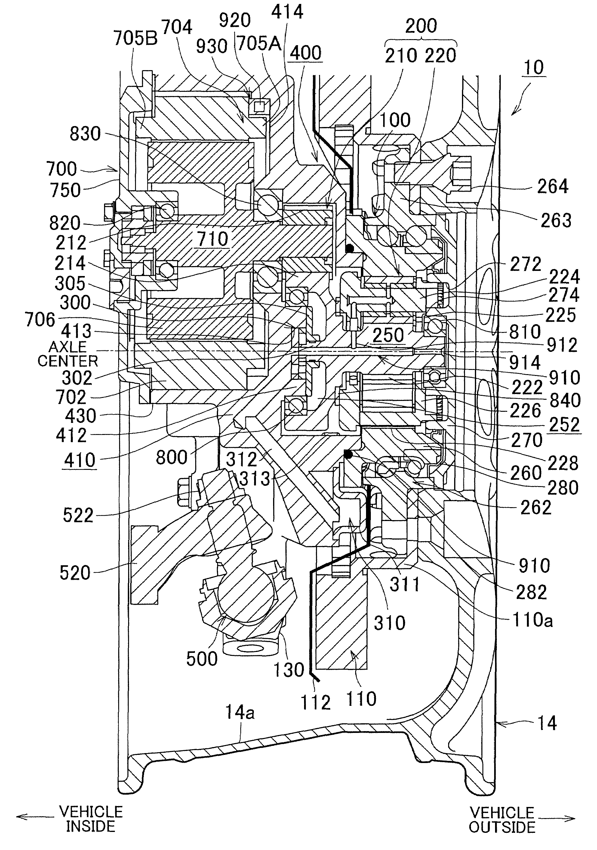
[0020]In the following description and the accompanying drawings, the present invention will be described in more detail in terms of exemplary embodiments. FIG. 1 is a sectional view of the main structure of a wheel assembly with an in-wheel motor according to one example embodiment of the invention. In the drawing, the tire, as well as the upper ⅓ or so of the wheel, is omitted.

[0021]A tire / wheel assembly 10 includes a wheel 14 to which a tire, not shown, is mounted. As will be described in detail later, the main portions of the constituent elements related to the motor are housed in a space enclosed by a rim inner peripheral surface 14a of the wheel 14. In the following description, the words “inside of the tire / wheel assembly” refer to the generally columnar space that is enclosed by the rim inner peripheral surface 14a of the wheel 14. However, expressions such as “a part is arranged inside the tire / wheel assembly” do not always mean that the entire part is housed completely wit...


PUM


Abstract

A motor has a stator core, a coil, a rotor, and a motor case in which the stator core, the coil, and the rotor are housed. The motor is also provided with a fluid carrying member that is arranged around a coil end of the coil in the motor case and has an inlet hole that is communicated with a fluid supply source and a distribution hole that is communicated with a space inside the motor case.

Description

INCORPORATION BY REFERENCE[0001]The disclosure of Japanese Patent Application No. 2006-219765 filed on Aug. 11, 2006, including the specification, drawings and abstract is incorporated herein by reference in its entirety.BACKGROUND OF THE INVENTION[0002]1. Field of the Invention[0003]The invention relates to an in-wheel motor and a wheel assembly with this in-wheel motor.[0004]2. Description of the Related Art[0005]Japanese Patent Application Publication No. JP-A-2005-73364, for example, describes a related wheel assembly with an in-wheel motor, which includes a motor, a rotating shaft that rotates according to output torque of the motor, an oil pump provided at one end of the rotating shaft, and an oil passage that supplies oil from the oil pump to an outer periphery of a stator core of the motor. In this wheel assembly with an in-wheel motor, the oil from the oil pump is supplied into the motor from the outer periphery of the stator core of the motor via an oil passage which has a...

Claims


Application Information

Patent Timeline
Patent Type & Authority Patents(United States)
IPC IPC(8): B60K1/00
CPCB60K7/0007B60K17/046F01M1/02H02K5/20H02K9/19B60K2001/003B60K2007/0038B60K2007/0061B60L2220/46F01M2001/0284Y02T10/641Y02T90/16Y02T10/64H02K5/203
Inventor MURATA, SATOSHITSUCHIDA, MICHITAKAURANO, HIROAKI
Owner TOYOTA JIDOSHA KK
Why Eureka
Try Eureka