Lunar resonant lighting

a technology of resonant lighting and lighting fixtures, applied in the direction of lighting and heating apparatus, coupling device connections, ways, etc., can solve the problems of wasteful large energy waste, waste of lighting fixtures and systems, etc., and achieve the effect of increasing engineering redundancy

Inactive Publication Date: 2010-11-09
WILLIS ANTON MICHAEL
View PDF18 Cites 116 Cited by
  • Summary
  • Abstract
  • Description
  • Claims
  • Application Information

AI Technical Summary

Benefits of technology

[0026]1) The processor can be programmed with an astronomical calculator which predicts lunar phase and brightness, and sun and moon rise and set times. This stored data can be compared to real-time data from the sensors in order to adjust to weather conditions. This also has the advantage of increased engineering redundancy.2) The digital processor can be programmed to compare the readings from all three sensors in a way that distinguishes diffuse from directional light. In the case of direct light coming from a single source, the photodiodes oriented at a 180° angular separation will never simultaneously be affected. In the case of diffuse light from cloud-scattered light pollution, however, all three sensors will simultaneously register a reading. In general, the average of the readings of the three photodiodes should be fairly constant as the moon moves through the sky, although the sensor oriented closest to the moon's position will register the highest reading, so that the moon may be “tracked”. The processor can thus differentiate between direct and diffuse light by comparing sensor inputs.3) An optical filter can be provided to differentiate light sources. Moonlight is a broad-spectrum light, being simply reflected sunlight. However, sodium and mercury vapor lamps, which are the main sources of urban light pollution, have narrow spectra and can be optically filtered. Such optical filters are used for astronomy applications. Providing such optical filters over the sensors prevents the system from responding to artificial sky glow, or nearby conventional streetlights.4) The sensor may be physically shielded from light sources near the horizon. Most direct artificial light sources, such as conventional streetlights and buildings, lie within a few degrees of the horizon. Masking these sources prevents the sensors from being affected by ground-source lighting.

Problems solved by technology

A great deal of energy is wasted on lighting fixtures and systems which do not take into account the amount of ambient light available to adequately light the target area.
Such systems would save significant amounts of energy and light pollution.
Current streetlights are prime examples of wasteful lighting fixtures and systems.
Streetlight fixtures and systems produce an excessive amount of illumination to light the intended area, and such “over-illumination” may carry significant costs.
The cost to produce this amount of electricity is enormous, and it is estimated that the energy production to light streetlamps results in approximately 3,000,000 tons of carbon emissions per year.
Current streetlight fixtures and systems also have negative safety and aesthetic impacts.
Glare and haze from over-illumination contribute to road accidents and decrease urban populations' ability to experience stars or moonlight on a nightly basis.
1) Moonlight is only 100,000th as bright as sunlight. Therefore, a moonlight sensor must be much more sensitive than those used in conventional streetlights.
2) Conventional streetlight photosensors detect ambient light levels, and do not need to measure direct sunlight. Moonlight, however, is sufficiently dim that accurate sensing requires that the sensor be pointed directly at the moon. However, the moon moves through a wide orbital arc each night, so that a typical flat sensor oriented in one direction will receive inaccurate readings due to the changing angle of incidence, depending on the relative position of the moon.
3) A photoreceptor of the necessary sensitivity will be affected by ambient cloud glow from light pollution. At low angles, it may also be affected by direct light from sources such as conventional streetlights and building lights. This is problematic because at low light levels, diffuse, non-directional light is less effective for human vision than direct, shadow-casting light, such as moonlight.
4) Typical High Intensity Discharge lamps used for streetlights do not dim continuously or efficiently.
While it is possible that the energy output for lighting fixtures and systems can be controlled manually (with a dimmer switch for example), such manual switching is often impractical and inefficient.
Manual dimming of lighting systems requires the expenditure of significant man hours to collect data relating to the amount of ambient light that is available and to control the dimmer accordingly.
Further, dimming an entire system would be ineffective because not every light in a particular system is targeting an area with the same amount of available ambient light.
Such ambient light changes can vary spatially and in unpredictable ways.
For example, when a cloud passes over a certain area of the lighting system, the lights under the cloud may need to project more light than those that are not under the passing cloud and, even then, the passing cloud would only affect the lighting efficiency of a certain number of lights for a certain period of time.
But that system would be limited in that it would likely be unable to detect the specific needs of a certain number of lights on the system depending on positioning of those lights and the changing weather or light producing conditions.

Method used


Image

  • Lunar resonant lighting
  • Lunar resonant lighting
  • Lunar resonant lighting

Examples


Embodiment Construction

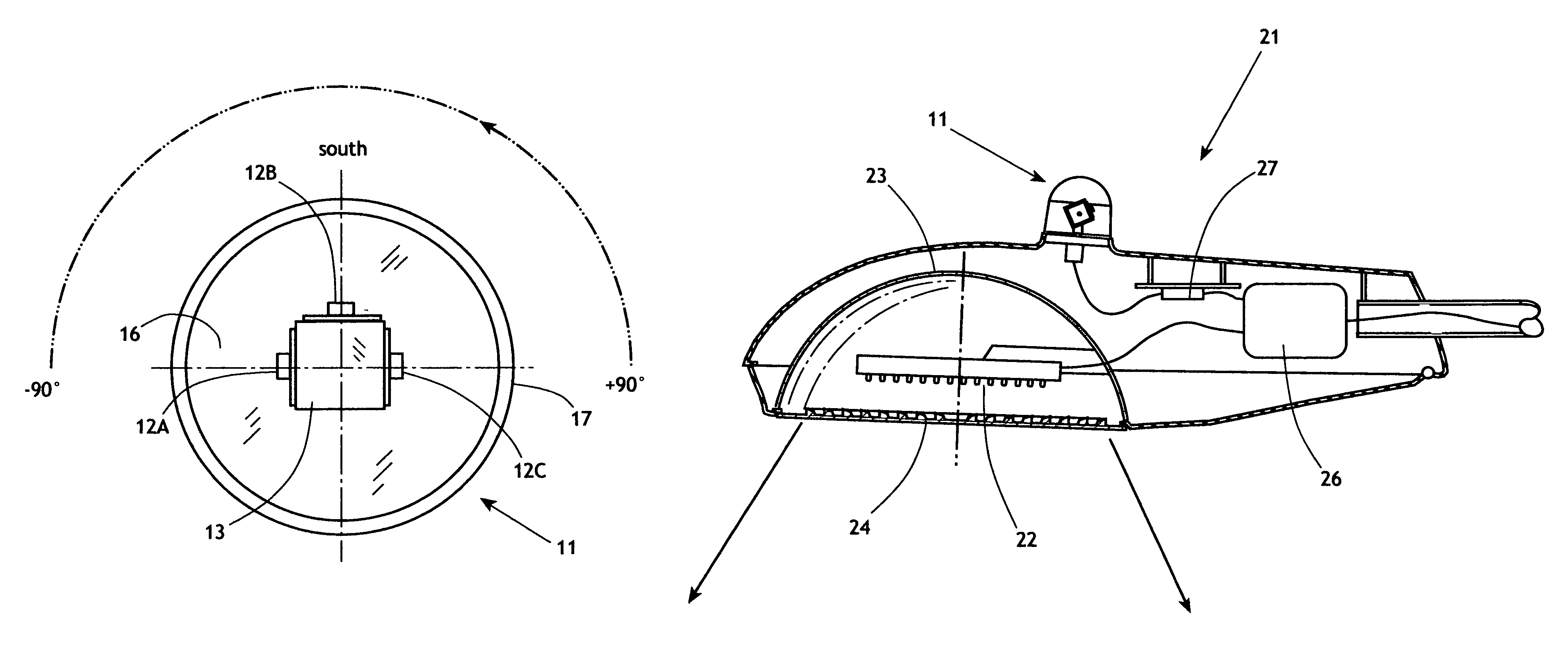
[0034]The present invention generally comprises a method and apparatus to control a lighting source such as a streetlight, and to modulate the output of the lighting source so that artificial illumination is reduced when moonlight is available to illuminate the area. As described below, the apparatus of the invention includes a sensor assembly for detecting moonlight in the night sky, an electronic circuit for processing the sensor signals in combination with moonrise and moonset data, and modulating the power applied to the lighting source in response to the intensity of the incident moonlight.

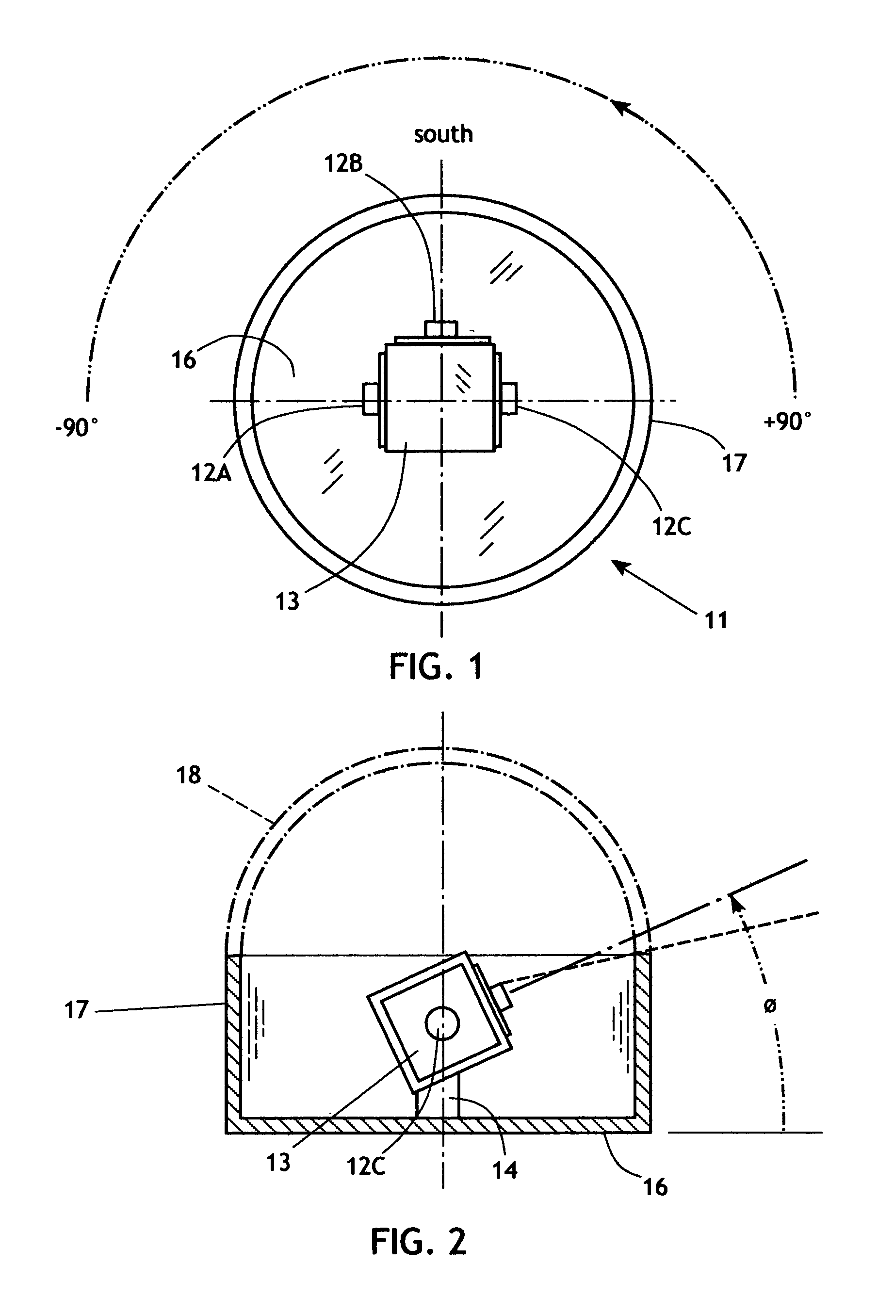
[0035]With regard to FIGS. 1 and 2, the sensor assembly 11 of the invention generally comprises a sensor array comprised of a trio of photodiodes 12A, 12B, and 12C support on a movable sensor housing 13. The photodiodes are directed outwardly from the housing 13 in a common plane, and are aimed at axes separated by 90°, as shown in FIG. 1. The housing 13 is supported on an adjustable mount 14...


PUM


Abstract

A method and apparatus to control a lighting source such as a streetlight and modulate the output of the lighting source so that artificial illumination is reduced when moonlight is available to illuminate the area. The apparatus includes a sensor assembly for detecting moonlight in the night sky, an electronic circuit for processing the sensor signals in combination with moonrise and moonset data, and modulating the power applied to the lighting source in response to the intensity of the incident moonlight.

Description

CROSS-REFERENCE TO RELATED APPLICATIONS[0001]This application claims the benefit of the priority of the filing date of U.S. Provisional Application 60 / 926,142, filed Apr. 25, 2007.FEDERALLY SPONSORED RESEARCH[0002]Not applicable.SEQUENCE LISTING, ETC ON CD[0003]Not applicable.BACKGROUND OF THE INVENTION[0004]1. Field of the Invention[0005]The present invention relates to area lighting fixtures and systems such as streetlights for highways, roads, walkways and other public areas, as well as porch, security, and garden lights for private outdoor uses. Alternatively, the fixtures and system can be used for indoor lighting such as that used in office buildings. The lighting fixtures and system uses discrete energy-saving light sources, such as LEDs, and a method for automatically adjusting the light and energy output based on the amount of ambient light available to light the intended target area. Streetlights, for example, inversely resonate with the amount of ambient moonlight, thus d...

Claims


Application Information

Patent Timeline
Patent Type & Authority Patents(United States)
IPC IPC(8): F21V14/00F21V37/00F21S13/10E01F9/00
CPCF21S8/086F21V23/0442H05B37/00H05B37/0218F21W2131/10F21W2131/103F21Y2101/02Y02B20/46Y02B20/72F21Y2115/10H05B47/11H05B47/155H05B47/165Y02B20/40
Inventor WILLIS, ANTON MICHAEL
Owner WILLIS ANTON MICHAEL
Why Eureka
Try Eureka