Tuning fork magnetometer

a magnetometer and tuning fork technology, applied in the field of magnetometers, can solve the problems of affecting the physical or electrical response of the magnetometer itself, affecting and the deficiency of the existing apparatus in one or more of these desirable features, etc., and achieve the effect of increasing the q of the apparatus

Inactive Publication Date: 2010-11-09
WSOU INVESTMENTS LLC +1
View PDF3 Cites 2 Cited by
  • Summary
  • Abstract
  • Description
  • Claims
  • Application Information

AI Technical Summary

Benefits of technology

[0011]In a preferred embodiment, the tuning fork is disposed within a vacuum enclosure, which increases the Q of the apparatus.

Problems solved by technology

Existing apparatus are deficient in one or more of these desirable features.
Consequently, extensive and complex calibrations are needed to use these magnetometers.
In other instances, components of magnetometers can become distorted when moving in response to a change in the magnetic field, thereby altering the physical or electrical response of the magnetometer itself.
In still other cases, the fabrication of magnetometers is complex and expensive.
They also require passing large currents through the coils during measurements, thereby consuming relatively large amounts of power.

Method used


Image

  • Tuning fork magnetometer
  • Tuning fork magnetometer
  • Tuning fork magnetometer

Examples


Embodiment Construction

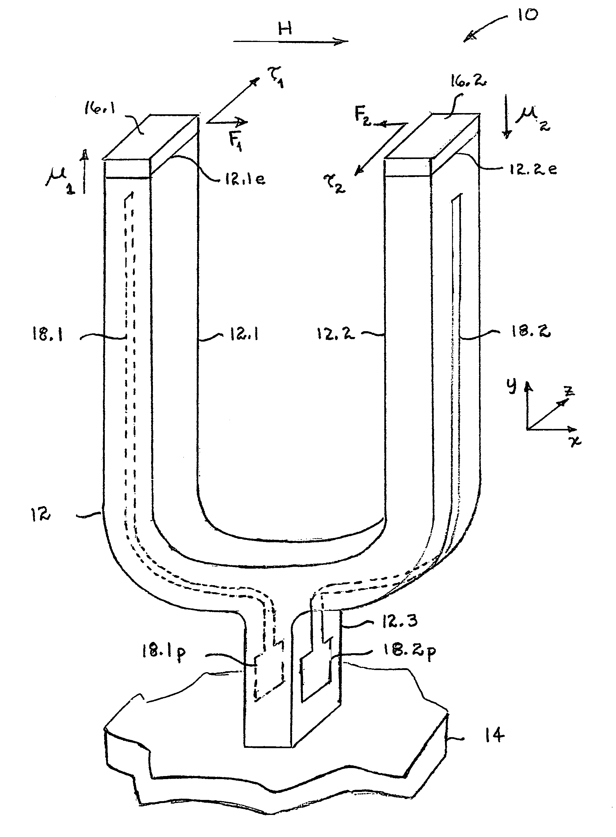
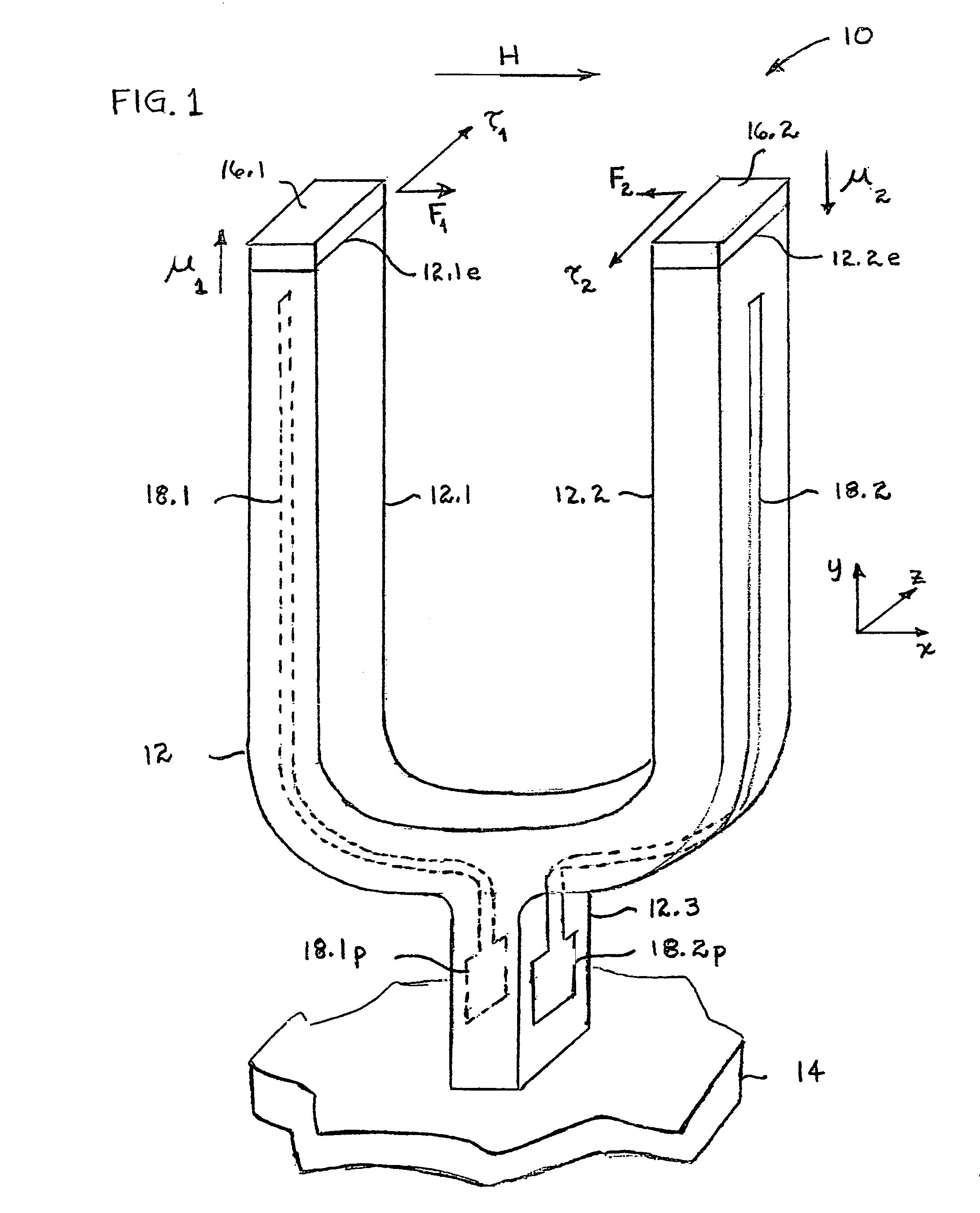
[0021]With reference now to FIG. 1, apparatus 10, when combined with a suitable drive circuit and detection subsystem discussed later, is configured to detect the magnitude and / or direction of a magnetic field H illustratively oriented in the +x-direction. Apparatus 10 is basically a loaded tuning fork; that is, apparatus 10 includes not only the tuning fork itself but also suitable electrodes and magnets affixed to the tuning fork. More specifically, apparatus 10 comprises a tuning fork 12, which includes a first tine 12.1 and a second tine 12.2 joined at a trunk 12.3. The latter is mounted on a support 14. Illustratively, tines 12.1 and 12.2 are oriented parallel to one another along the y-axis. In accordance with one aspect of our invention, a magnet 16.1 is disposed on the end surface (or tip) 12.1e of first tine 12.1, and a magnet 16.2 is disposed on the end surface (or tip) 12.2e of second tine 12.2. Magnets 16.1 and 16.2 exhibit magnet moments (e.g., dipoles) μ1 and μ2, respe...


PUM


Abstract

Apparatus comprises a tuning fork having first and second tines, a first magnet disposed on the first tine, and a second magnet disposed on the second tine. In one embodiment the magnets comprise permanent magnets; in another they comprise electromagnets. In a preferred embodiment the magnets have magnetic moments oriented essentially parallel to the axis of the tines and anti-parallel to one another. In operation, the apparatus is made to oscillate at or near its resonant frequency, and in the presence of a magnetic field a parameter of the oscillation (e.g., its frequency, phase or amplitude) is altered in a fashion that allows the magnitude or direction of the magnetic field to be determined. In a preferred embodiment, the tuning fork is disposed within a vacuum enclosure, which increases the Q of the apparatus.

Description

BACKGROUND OF THE INVENTION[0001]1. Field of the Invention[0002]This invention relates to magnetic field detectors in general and to magnetometers that employ tuning forks in particular.[0003]2. Discussion of the Related Art[0004]The measurement of magnetic fields has many applications, such as navigating vessels, detecting magnetic metal in security settings, and prospecting for oil and minerals. In these settings there is a long-standing need for inexpensive, low-power apparatus to detect small changes in magnetic fields over large ranges. Existing apparatus are deficient in one or more of these desirable features.[0005]For example, certain microelectromechanical (MEM) magnetometers measure changes in magnetic fields over only a small range of magnetic intensity. Thus, multiple magnetometers, each adjusted to a different range of magnetic field intensity, may be needed to cover a desired range. Also, some magnetometers respond nonlinearly to changes in the magnetic field intensity...

Claims


Application Information

Patent Timeline
Patent Type & Authority Patents(United States)
IPC IPC(8): G01R33/02
CPCG01R33/02G01R33/028
Inventor BLUMBERG, GIRSH ELIASDENNIS, BRIAN SCOTT
Owner WSOU INVESTMENTS LLC
Why Eureka
Try Eureka