Optical scanner with improved scan time

a scanning time and optical scanner technology, applied in the field of high scanning frequency methods and equipment, can solve the problems of limiting the rate at which objects are scanned, limitations of conventional optical scanning systems, and limitations of focused beam movement rate, etc., to achieve simple and less expensive objectives

Active Publication Date: 2010-11-09
ILLUMINA INC
View PDF491 Cites 28 Cited by
  • Summary
  • Abstract
  • Description
  • Claims
  • Application Information

AI Technical Summary

Benefits of technology

[0013]Optionally, the optomechanical system may further comprise a scan generator that includes a pair of phase-locked resonant scanning mirrors for generating a curved scan pattern. The resonant scanning mirrors are kept out of phase by 90 degrees so that one scanner is at maximum deflection when the other scanner is at its nominal center angle. The amplitude of both scanners are varied at a fixed frequency so as to produce a “spiral” scan pattern that has high scan efficiency.
[0018]2) The scanned laser beam always subtends the pupil of the objective lens at the same field angle and location due to the rotationally symmetric nature of the optical scanning system. This allows simpler and less expensive objectives to be used to focus the beam to a diffraction limited spot. In contrast, a traditional “f-theta” lens system in the prior art generally requires a many-element complex design to function correctly.

Problems solved by technology

However, conventional optical scanning systems experience certain limitations.
For example, conventional optical scanning systems have limitations on the rate at which the focused beam moves across the area of interest, which in turn limits a rate at which objects are scanned.

Method used


Image

  • Optical scanner with improved scan time
  • Optical scanner with improved scan time
  • Optical scanner with improved scan time

Examples


Embodiment Construction

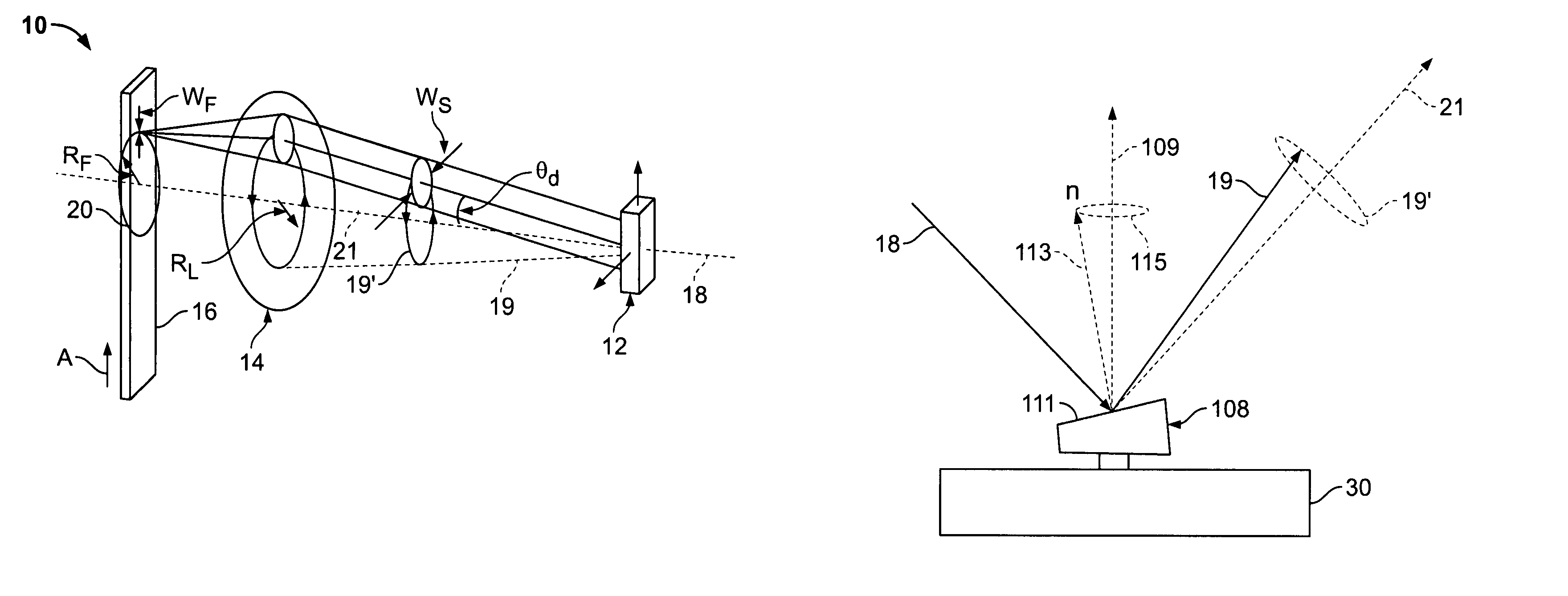
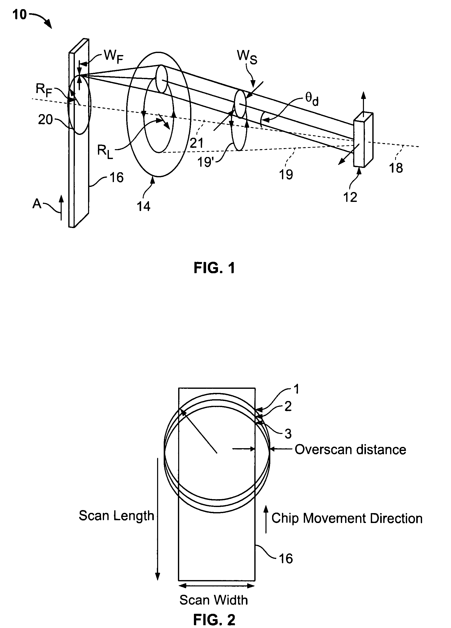
[0027]FIG. 1 shows an embodiment of the present invention in the form of an optomechanical system generally indicated as 10 for rapidly scanning a 2-dimensional plane with successive circles (see FIG. 2). The optomechanical system 10 includes a conical scan generator 12 and an objective lens 14 arranged in a desired relation to an object (substrate) 16. Relative movement is provided between the object 16 and the optomechanical system 10, such as by moving the object 16 in the direction of the arrow A.

[0028]In operation, the conical scan generator 12 responds to an incident beam of light (such as a laser beam) generally indicated as 18, and directs a scanned laser beam generally indicated as 19 (also referred to as an exit laser beam) on the objective lens 14 in a desired pattern. The exit laser beam 19 scans around the objective lens 14 at a fixed radius RL with a fixed input angle θd. When scanned in this manner, the exit laser beam 19 moves along a conical direction before impingi...


PUM


Abstract

A method and apparatus is provided for scanning an object, featuring scanning an incident beam in a substantially curved scan pattern; and moving an object at a predetermined rate along an axis substantially orthogonal to a plane of the curved scan pattern so that a two dimensional image can be formed by successive passes of a circularly scanned spot. In particular, a laser beam scans around an objective lens at a fixed radius RL with a fixed input angle θd. When scanned in this manner, the laser beam before the objective lens forms a “cone” of directions (so herein it is referred to as a “conical scan”). Scanning in this fashion produces the curved scan pattern at the object (substrate). By moving the object (substrate) at the predetermined rate along the axis orthogonal to the plane of the curved scan pattern, the two dimensional image can be formed by successive passes of the circularly scanned spot.

Description

RELATED APPLICATION[0001]The present application relates to and claims priority from Provisional Application Ser. No. 60 / 791,138 filed Apr. 10, 2006, titled “OPTICAL SCANNER WITH IMPROVED SCAN TIME”, the complete subject matter of which is hereby expressly incorporated in its entirety.BACKGROUND OF INVENTION[0002]The present invention generally relates to methods and apparatus for scanning an object and more particularly to methods and apparatus for scanning a moving object at high scan frequency. As used throughout, the phrase “scan frequency” is used to mean the inverse time it takes to complete scanning of one line of a two-dimensional image of a series of (not necessarily straight) lines.[0003]Conventional optical systems exist that scan a focused spot across an area for use in many applications, including high-resolution reprographics and fluorescent image acquisition. Generally, conventional optical systems direct a series of successive line scans of a tightly focused beam acr...

Claims


Application Information

Patent Timeline
Patent Type & Authority Patents(United States)
IPC IPC(8): G02B26/08
CPCG02B26/0816G02B26/0891G02B26/108
Inventor MOON, JOHN A.FOURNIER, DAVID R.
Owner ILLUMINA INC
Why Eureka
Try Eureka