
Drapery motor remote activation by manual drapery pull

a drapery motor and remote activation technology, applied in the field of motorized drapery system activation, can solve the problems of fabric or system damage, cord drive motors are usually difficult to conceal, and require more maintenance for cord adjustment, so as to prevent damage to the electric drive system

Inactive Publication Date: 2010-11-16
VRIELINK GERRIT JAN
View PDF16 Cites 24 Cited by
  • Summary
  • Abstract
  • Description
  • Claims
  • Application Information

AI Technical Summary

Benefits of technology

"The invention is a new system for remotely controlling the operation of a motor drive for a drapery system. It uses a wireless transmitter and a sensor to detect when someone pulls on the drapes, which triggers the motor to move the drapes. This eliminates the need to disconnect the main carrier from the motor to prevent damage, and allows for the use of standard motors with wireless receivers. The system can also sense the direction of the pull and ensure the motor operates in the same direction. Overall, the invention provides a safer and more convenient way to control the operation of the motor drive for drapery systems."

Problems solved by technology

Especially on cord actuated systems, the required force to pull a drapery open or closed by means of pulling the fabric instead of the cord may require considerable force and result in damage to the fabric or the system.
Cord drive motors are usually hard to conceal, tend to require more maintenance for cord adjustments, and are usually less powerful than direct drive motors.
An unsuspecting user may be tempted to start pulling on the fabric to open or close a drape which will require rotation of the motor.
However, since such rotation is prevented by the direct drive connection, this could create damage to the mechanism if excessive force were applied by the user.
A disadvantage of the disconnect method is that after disconnecting, the drapery cannot be moved under electrical power until the drive is reconnected.
The disadvantage of this method is the requirement for the user to create a pulling force in a horizontal direction which, especially in heavier draperies, may be cumbersome.
A further disadvantage is that the method requires that the motors be equipped with the specific current sensing technology.
The disadvantage of this system is that it is most commonly operated by drive motors that are started and stopped by means of current sensing.
Such motor require considerable torque surges and as a consequence tend to be noisy.
Because of space considerations, the microdimensions make the system extremely sensitive to wear and most commonly permit only very small drapery weight loads.
The disadvantage of this system is that there is only one spring to handle both the drapery load function and the locking spring function.
The use of a single spring for this dual purpose severely limits the maximum allowable load on the arm.
Currently this is commonly limited to a maximum of 0.5 kg vertical load.
The load limitation caused by the single arm and single spring concept of the prior art places severe limitations on the motorized drapery system.
Weight limitations impose severe restrictions on the range of applications.
Furthermore, the range between the drapery load and the maximum allowable weight due to the spring capacity can easily be exceeded, which would cause the load to lower the levered arm and free the connection between master carrier and drive belt.
This would result in a malfunction of the motorized system when power is applied.

Method used


Image

  • Drapery motor remote activation by manual drapery pull
  • Drapery motor remote activation by manual drapery pull
  • Drapery motor remote activation by manual drapery pull

Examples


Embodiment Construction

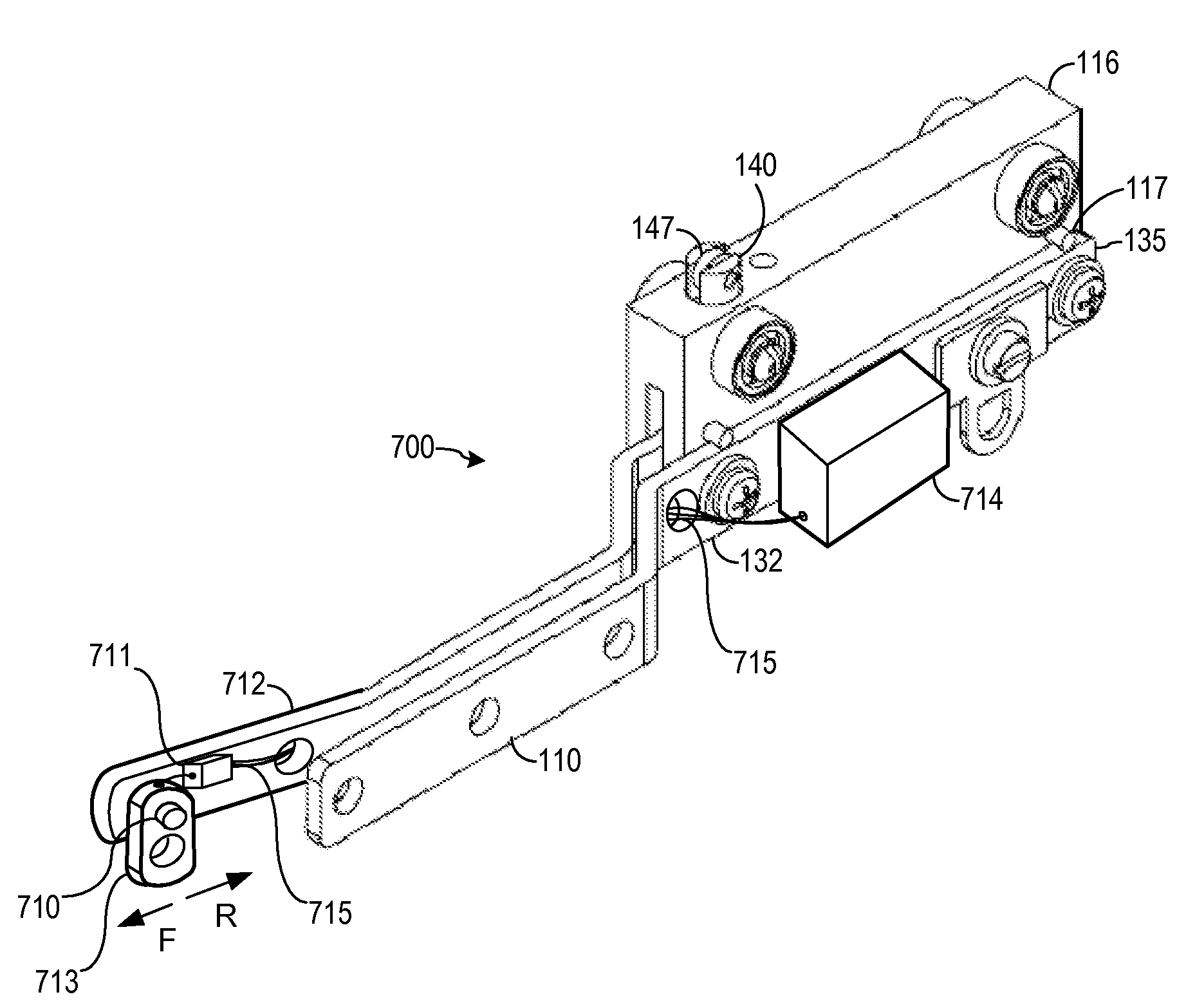
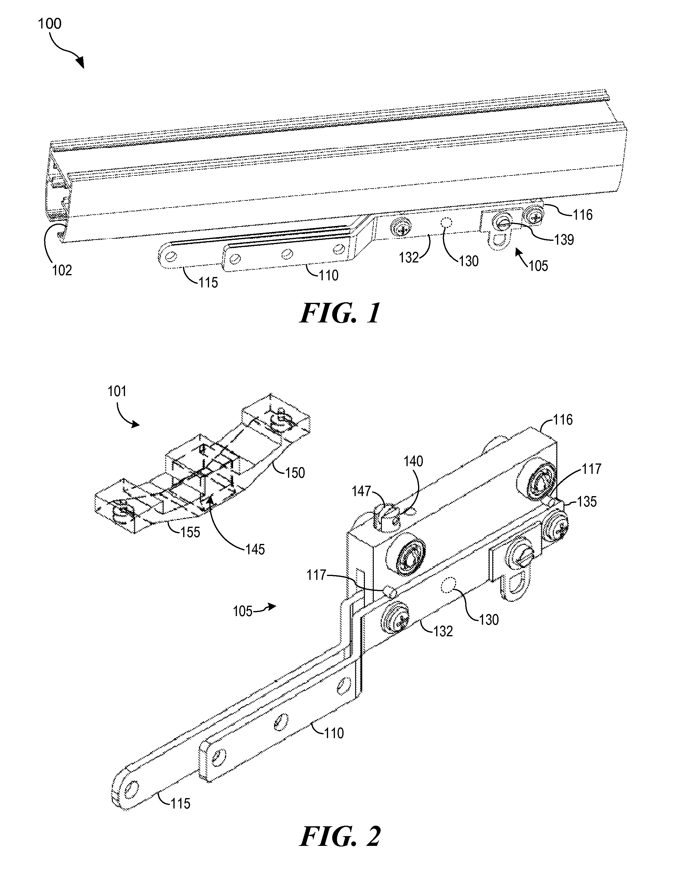
[0042]Turning now to the drawings in detail, and initially to FIGS. 1, 2 and 3 thereof, one embodiment of a master carrier drive block assembly 100 with a mechanical disengager and no RF or IR transmitter. Master carrier block assembly 100, which can be slideably disposed inside headrail 102, is made up of two main components: the locking block section 101 that is connected to the drive belt (not shown) and the master carrier block section 105 that is attached to the forward end of the fabric of the drapes (not shown).

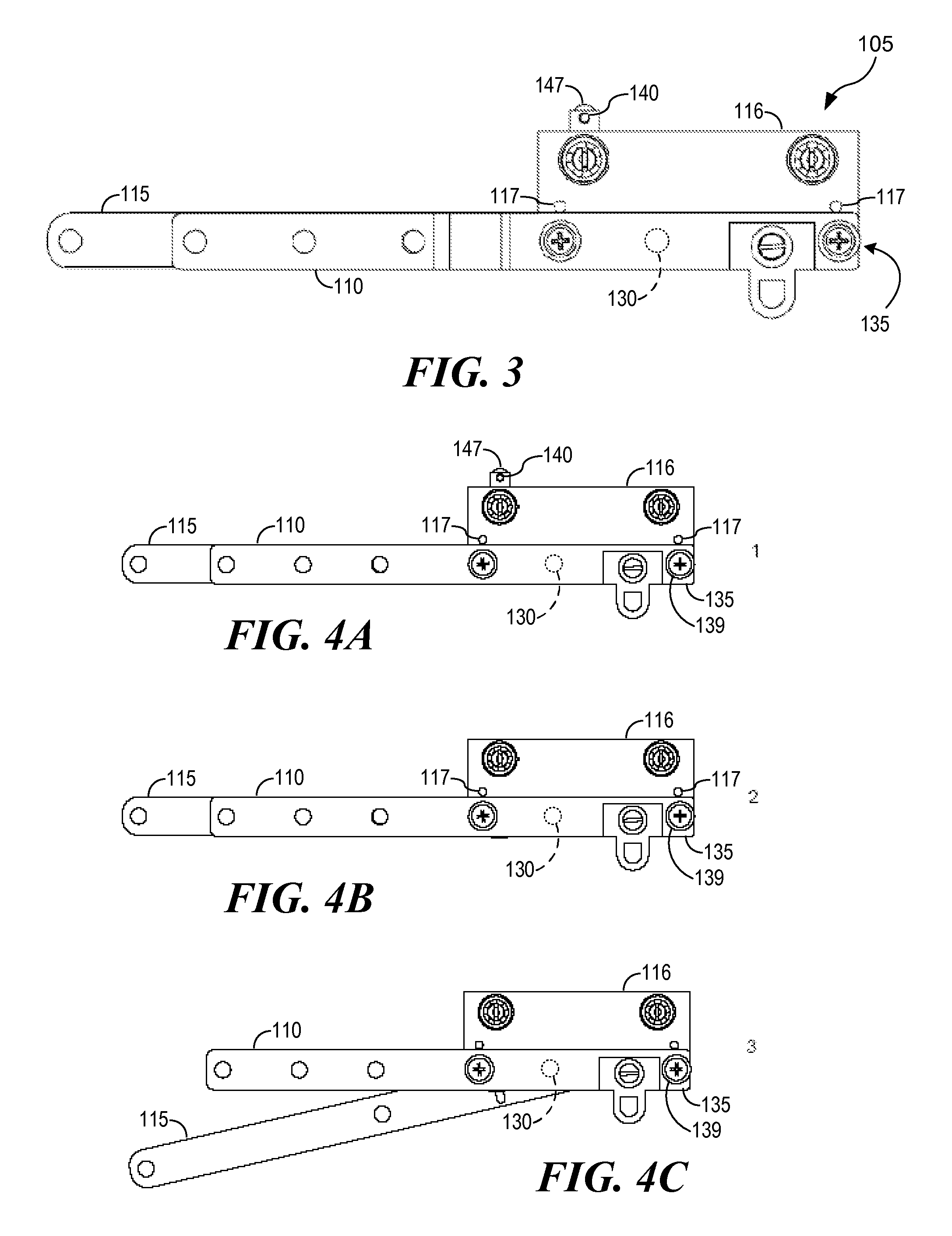
[0043]Turning now to FIGS. 4A-4C and 5A-5D, an elevation view of the master carrier block wherein the spring function required to carry the drapery load is separated from the spring function of the locking mechanism that disengageably connects the master carrier block 105 to the locking block section 101 connected to the drive belt (not shown). In the embodiment depicted, the invention further uses dual metal arms 110 and 115 mounted to master carrier block body 116. O...


PUM


Abstract

A drapery master carrier for a drapery electric drive system is provided having a built-in wireless transmitter and a sensor to determine whether a manual pull is being applied to the drapes. The sensor is operatively connected to or incorporated into the wireless transmitter such that sensing by the sensor of a manual pull applied to the drapes will activate the wireless transmitter to transmit a signal to a motor drive controller receiver to drive the motor.

Description

FIELD OF THE INVENTION[0001]The present invention relates to the activation of motorized drapery systems. In particular, the present invention provides the ability to automatically start the motorized opening or closing operation of the draperies by activating motor operation by means of a radio frequency (RF), infrared (IR) or other wireless remote signal emitted from a transmitter incorporated in the master carrier assembly, the remote signal being initiated by a manual pull on the drapes.BACKGROUND[0002]Drapery support systems that permit opening and closing of the draperies are well known. Such systems commonly consist of an aluminum, steel or plastic headrail that contains a series of rollers or sliding carriers. These carriers have drapery fabric or material connected to them by some form of a drapery hook or other means. Depending on the form of pleating, these carriers are spaced at approximately three inches. Also depending on the pleating system, the individual carriers ma...

Claims


Application Information

Patent Timeline
Patent Type & Authority Patents(United States)
IPC IPC(8): A47H15/00
CPCA47H5/0325Y10T16/376Y10T16/354Y10T16/372
Inventor VRIELINK, GERRIT JAN
Owner VRIELINK GERRIT JAN
Learn More