
Eye safety protection from high power laser light

a laser light and safety protection technology, applied in the direction of optical radiation measurement, discharge tube/lamp details, instruments, etc., can solve the problems of serious eye injury, difficult to know when potentially harmful radiation levels are present in the environment, and human beings are at risk of being exposed to harmful laser radiation levels

Inactive Publication Date: 2010-11-16
CUBIC CORPORATION
View PDF4 Cites 15 Cited by
  • Summary
  • Abstract
  • Description
  • Claims
  • Application Information

AI Technical Summary

Benefits of technology

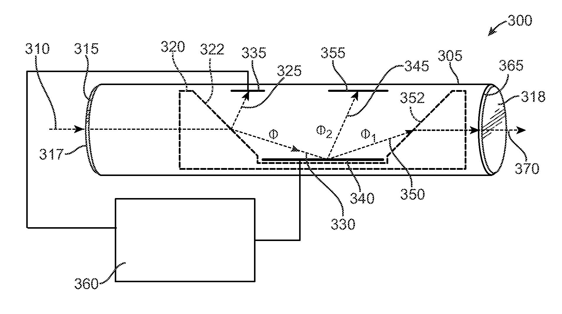
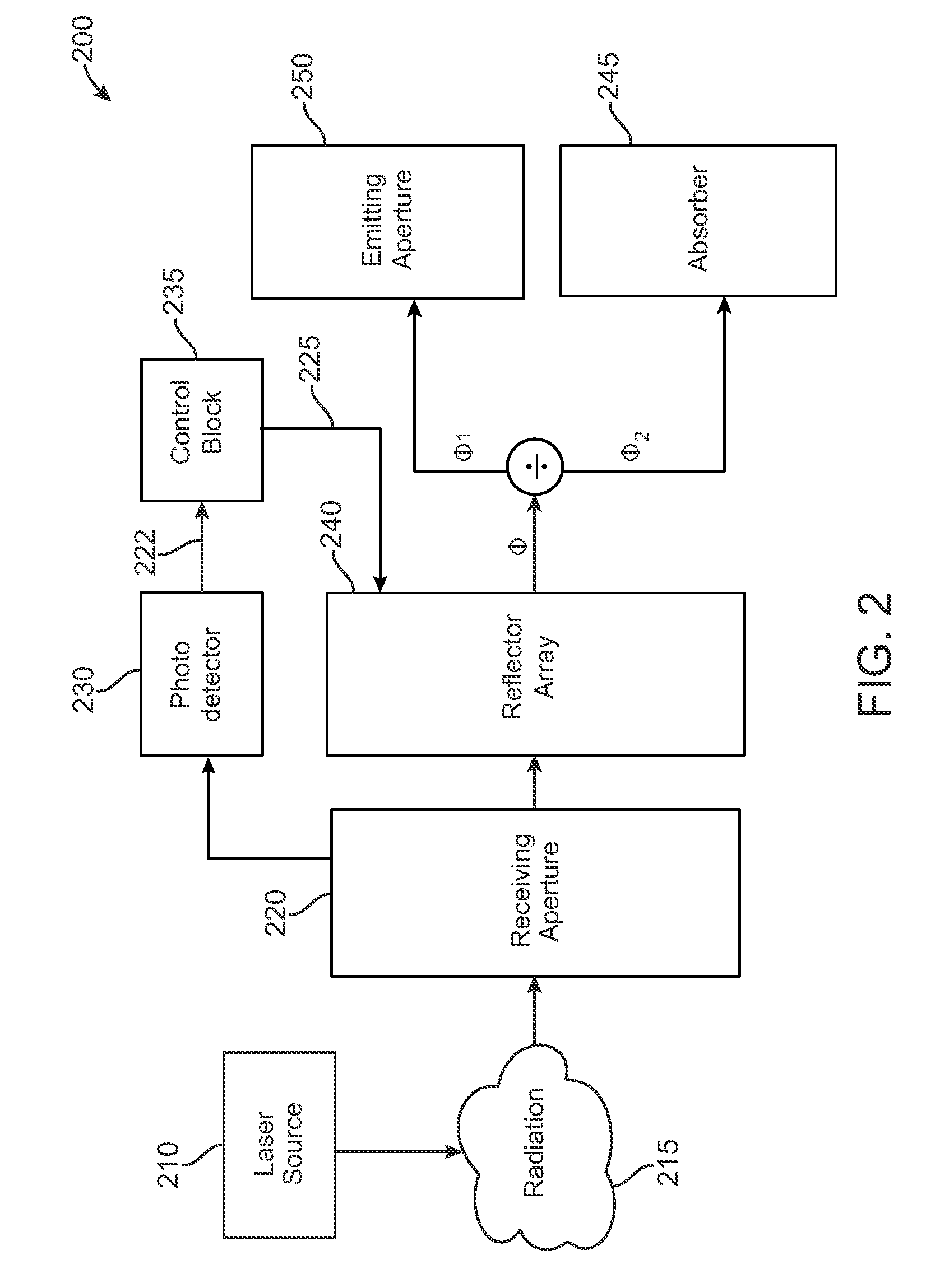
[0008]In another embodiment, the control signal is operative to cause the reflector array to divert substantially all of the radiation away from the incident path if the level of the radiation is detected as exceeding a threshold value. Alternatively, the reflector array may adjust the first part of the radiation such that a level of the second part does not exceed a threshold value. The threshold value, for example, may be established in accordance with a maximum permissible exposure level of the ANSI Z136 standard for eye safety. In one embodiment, the device also includes an absorber for receiving the first part of the radiation and dissipating its energy as well as a warning indicator to provide a visual cue when harmful levels of radiation are detected.

Problems solved by technology

As lasers are used in increasing numbers throughout society, human beings run the risk of being exposed to harmful levels of laser radiation.
As a result, it can be difficult to know when potentially harmful levels of radiation are present in the environment.
In addition, laser radiation can cause serious eye injury by damaging the cornea, retina, and lens.
For example, ultraviolet radiation may cause lens damage such as cataracts, whereas exposure to infrared radiation often results in retinal and corneal burns.
Unfortunately, strict adherence to safety standards is not always possible.
For example, military personnel may be exposed to high-powered lasers on the battlefield without knowing the type of laser involved and exposure may occur in situations where the use of cumbersome eye protection is not an option.
Similarly, malicious use of laser devices may create serious hazards to aviation and maritime personnel using high-powered optics to monitor the passage of planes, ships, etc.

Method used


Image

  • Eye safety protection from high power laser light
  • Eye safety protection from high power laser light
  • Eye safety protection from high power laser light

Examples


Embodiment Construction

[0018]In accordance with embodiments of the present invention, a laser safety device and method of protecting against harmful levels of radiation are disclosed. In one embodiment, the laser safety device includes a housing with first and second apertures. The device also includes a photodetector that generates a first signal corresponding to a level of radiation entering the housing through the first aperture. A control circuit receives the first signal from the photodetector and generates a control signal in response thereto. The control signal actuates a reflector array and causes one or more reflectors in the array to divert a first part of the radiation away from an incident path extending from the first aperture to the second aperture and to allow a second part of the radiation to continue along the incident path towards the second aperture.

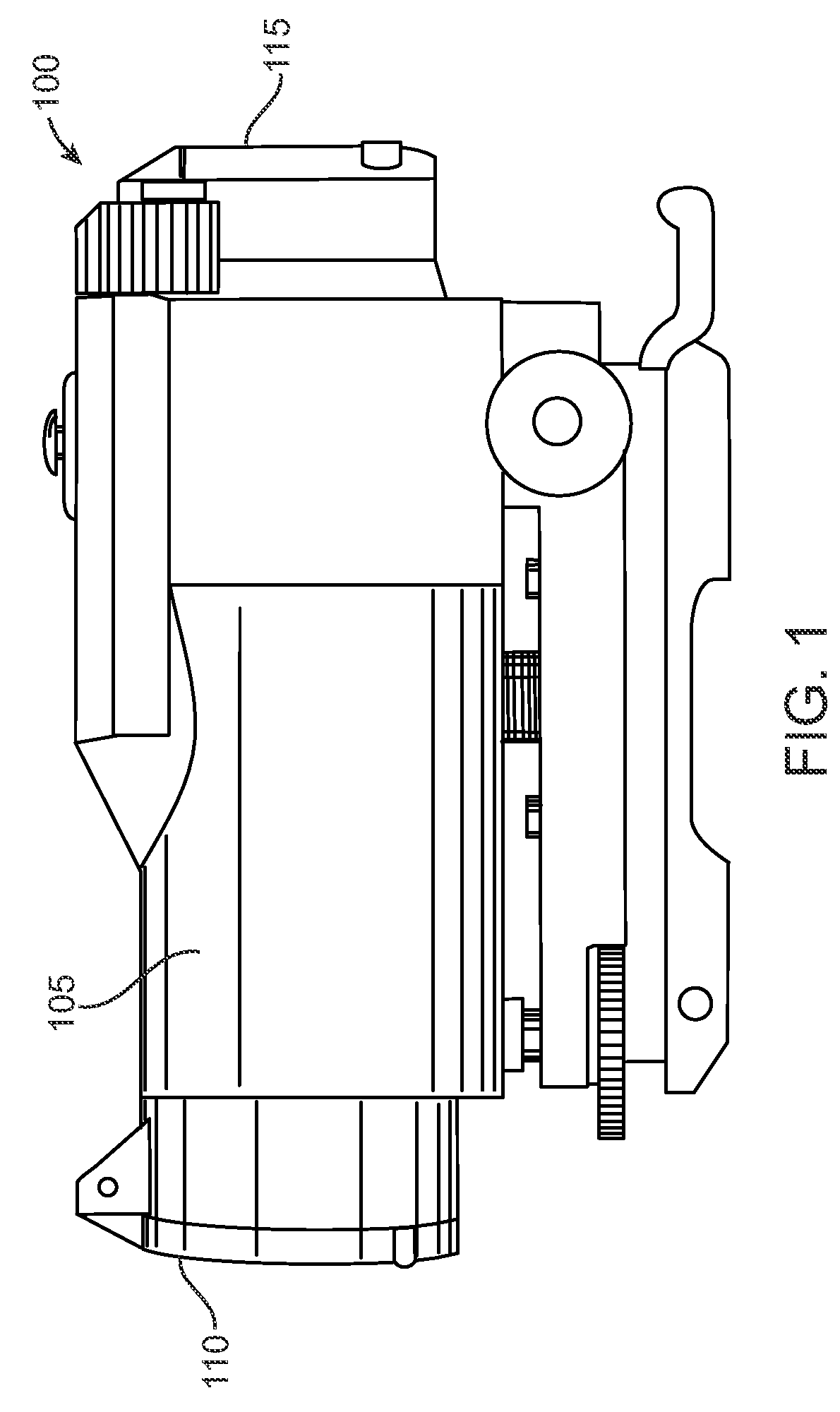
[0019]FIG. 1 shows an exemplary laser safety device 100 according to one embodiment of the present invention. As shown, device 100 is a wea...


PUM


Abstract

A laser safety device and method of protecting against harmful levels of radiation. The device includes a housing with first and second apertures. A photodetector generates a first signal corresponding to a level of radiation entering the housing through the first aperture. A control circuit receives the first signal and generates a drive signal based upon the level of the radiation. A reflector array which can include micro-electro-mechanical mirrors receives the drive signal and diverts a first part of the radiation away from an incident path extending from the first aperture to the second aperture. The reflector array allows a second part of the radiation to continue along the incident path at a safe level towards the second aperture. Optionally, the reflector array blocks the incident path so that substantially no radiation passes to the second aperture if unsafe levels are detected.

Description

CROSS-REFERENCES TO RELATED APPLICATIONS[0001]This application claims the benefit of U.S. Provisional Application No. 60 / 868,290 filed on Dec. 1, 2006 and entitled HIGH POWER LASER EYE SAFETY PROTECTION which is incorporated herein by reference.BACKGROUND OF THE INVENTION[0002]As lasers are used in increasing numbers throughout society, human beings run the risk of being exposed to harmful levels of laser radiation. Laser devices can generate radiation at a number of different wavelengths which can be either visible or invisible to the human eye. As a result, it can be difficult to know when potentially harmful levels of radiation are present in the environment.[0003]The effects of exposure to harmful levels of laser radiation are well known and include mild to severe skin burns. In addition, laser radiation can cause serious eye injury by damaging the cornea, retina, and lens. Different wavelengths of laser radiation are associated with different types of eye injury. For example, u...

Claims


Application Information

Patent Timeline
Patent Type & Authority Patents(United States)
IPC IPC(8): G01J1/20H01J40/14H01J3/14
CPCG01S7/4804G01S7/495
Inventor RIPINGILL, JR., ALLEN E.D'SOUZA, CLARKCOUNTER, JIM MILTON
Owner CUBIC CORPORATION
Learn More