Position sensor system

a sensor system and position sensor technology, applied in the field of determining position, can solve the problems of motors with contact bearings that may wear, fail, and eventually fail, and achieve the effects of reducing manufacturing costs, reducing production costs, and improving production efficiency

Active Publication Date: 2010-11-16
BOOKS AUTOMATION US LLC
View PDF34 Cites 41 Cited by
  • Summary
  • Abstract
  • Description
  • Claims
  • Application Information

AI Technical Summary

Benefits of technology

[0006]It would be advantageous to provide a system of sensors and scales attached to a motor reactive element such as a rotor to provide accurate position and eccentricity measurements.
[0007]It would also be advantageous to have a sensor system that utilizes magnetic flux density in order to accurately measure the position of a rotor and to accurately measure the scales that may be attached to or integral with the reactive element.
[0008]It would be also be advantageous to have a motor feedback system that simultaneously measures the eccentricity and orientation of the rotor with respect to the stator without using two types of sensors.

Problems solved by technology

In certain applications, materials must be processed in a controlled, clean atmosphere where microscopic contaminates may represent a severe problem.
In those applications, cleanliness may be directly related to yield, which may in turn affect cost.
Motors with contact bearings may wear, produce particulate contamination, and eventually fail due to the hostile environment.
Bearings may also exhibit an unacceptable amount of vibration and play before failing.
While self-bearing motors may provide a viable alternative for these applications, it would be undesirable to penetrate or invade the hostile environment with cables or other conductors in order to measure the exact position of the reactive element.
Optical techniques may also be disadvantageous because they may require a “window” into the hostile environment that may likewise compromise the integrity of an enclosure containing the environment.

Method used


Image

  • Position sensor system
  • Position sensor system
  • Position sensor system

Examples


Embodiment Construction

[0031]Although the presently disclosed embodiments will be described with reference to the drawings, it should be understood that they may be embodied in many alternate forms. It should also be understood that In addition, any suitable size, shape or type of elements or materials could be used.

[0032]The exemplary embodiments are directed to position sensing systems for motors that provide a desired level of accuracy and repeatability. Additional embodiments include systems for use with motors in hostile or clean environments, in particular, robot drive applications where the rotor and stator may be atmospherically isolated from each other.

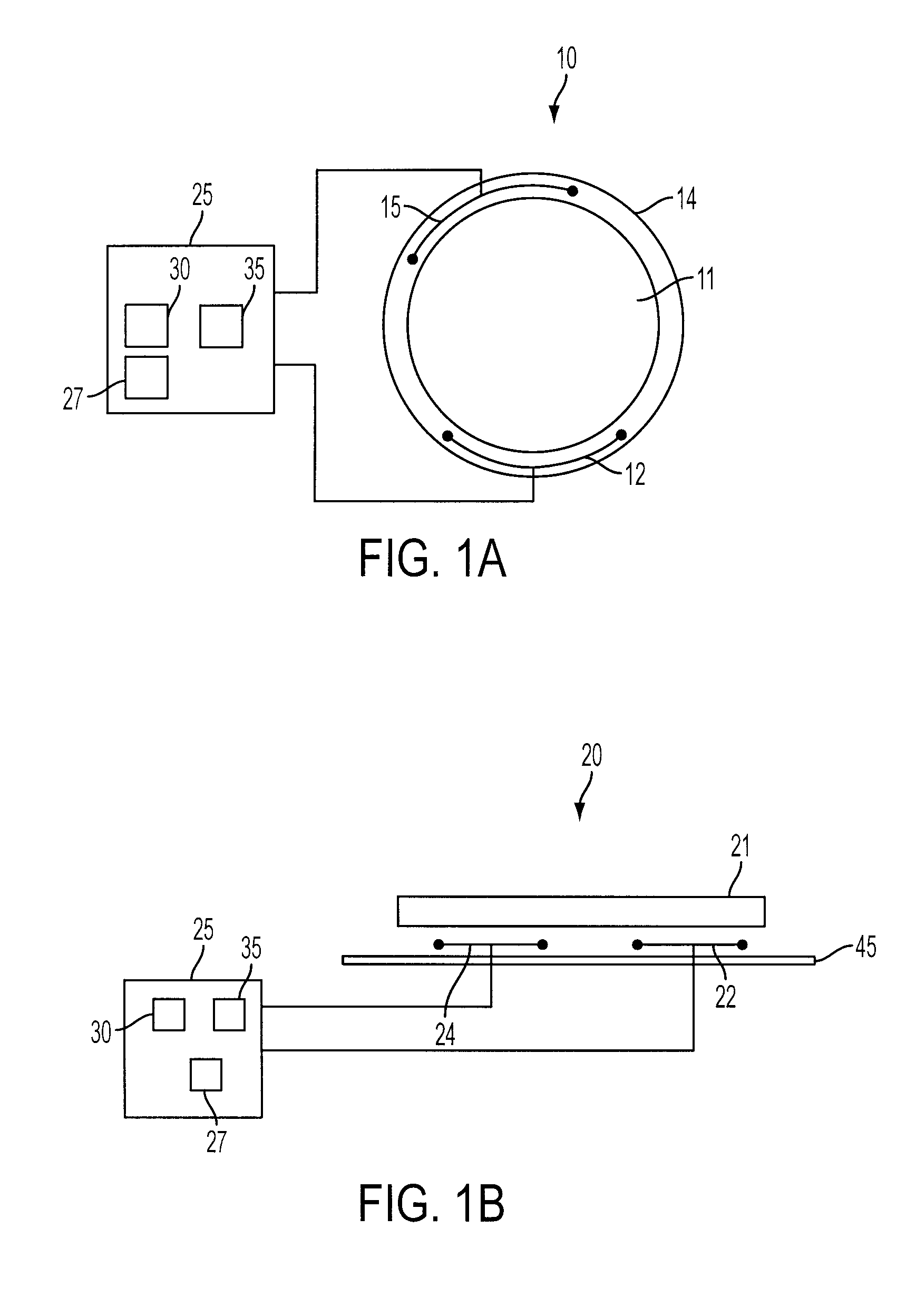
[0033]FIG. 1A shows a schematic diagram of an exemplary motor 10 suitable for practicing the embodiments disclosed herein. Although the presently disclosed embodiments will be described with reference to the drawings, it should be understood that they may be embodied in many alternate forms. It should also be understood that any suitable size, shap...


PUM


Abstract

A sensing mechanism includes a magnetic source, a magnetic flux sensor, a sensor backing on which the magnetic source and flux sensor are mounted, and a ferromagnetic target, where the magnetic source, magnetic flux sensor, and ferromagnetic target are positioned to form a magnetic circuit from the magnetic source to the target, from the target to the sensor, and returning to the magnetic source through the sensor backing.

Description

[0001]This application claims the benefit of U.S. Provisional Patent application 60 / 946,686, entitled: POSITION FEEDBACK FOR SELF BEARING MOTOR, filed 27 Jun. 2007, which is incorporated by reference herein in its entirety.[0002]This application is related to U.S. patent application Ser. No. 11 / 769,688, entitled: COMMUTATION OF AN ELECTROMAGNETIC PROPULSION AND GUIDANCE SYSTEM, filed 27 Jun. 2007, U.S. patent application Ser. No. 11 / 769,651, entitled: REDUCED-COMPLEXITY SELF-BEARING BRUSHLESS DC MOTOR, filed 27 Jun. 2007, U.S. Provisional Patent application 60 / 946,693, entitled: MOTOR STATOR WITH LIFT CAPABILITY AND REDUCED COGGING CHARACTERISTICS, filed 27 Jun. 2007, and U.S. Provisional Patent application 60 / 946,687, entitled “ROBOT DRIVE WITH MAGNETIC SPINDLE BEARINGS”, filed 27 Jun. 2007, all of which are incorporated by reference herein in their entirety.BACKGROUND[0003]The presently disclosed embodiments are directed to determining position, in particular to providing non-cont...

Claims


Application Information

Patent Timeline
Patent Type & Authority Patents(United States)
IPC IPC(8): G01B7/14G01B7/30
CPCG01D5/147G01D5/2451G01B7/142G01B7/023G01B7/046G01D5/145
Inventor MOURA, JAIROHOSEK, MARTINKRISHNASAMY, JAYPARANAY, JEFF
Owner BOOKS AUTOMATION US LLC
Why Eureka
Try Eureka