Wireless power storage device comprising battery, semiconductor device including battery, and method for operating the wireless power storage device

a power storage device and wireless technology, applied in secondary cells, electrochemical generators, instruments, etc., can solve the problems of reducing power consumption in order to cope with the operating time, limiting the durability of batteries, and troublesome charging for users, so as to achieve the effect of convenient use of wireless power storage devices

Inactive Publication Date: 2010-11-23
SEMICON ENERGY LAB CO LTD
View PDF35 Cites 39 Cited by
  • Summary
  • Abstract
  • Description
  • Claims
  • Application Information

AI Technical Summary

Benefits of technology

[0007]However, the frequency of use of movable electronic devices has risen steadily, and there is a limit to improving the durability of batteries and reducing power consumption in order to cope with the operating time. Further, for charging a battery which is a power supply built into a movable electronic device, there have not been any methods other than charging from a charger through an AC adaptor via a household alternating current power supply or charging from a commercially available primary battery. Therefore, there has been a problem in that charging has been troublesome for users, and it has been necessary for users to take an AC adaptor or a primary battery which is a power supply means with them when they are moving about outdoors, which is burdensome.
[0009]Therefore, an object of the present invention is to make charging a battery of a power storage device which includes the battery easier. Further, an object of the invention is to provide a wireless power storage device which can transmit and receive information without the task of replacing a battery for drive power supply, which arises when the battery depletes over time, being performed, and to provide a semiconductor device which includes the wireless power storage device.
[0023]In the invention, by providing a wireless power storage device with a battery capable of wireless charging, charging of the battery provided in the wireless power storage device is made easier, and a wireless power storage device that is capable of transmitting and receiving information to and from the outside, without the task of replacing the battery due to depletion of the battery over time being performed, can be provided. Further, when the battery is charged over a certain period of time by receiving electromagnetic waves, and stored electrical power is discharged in pulses, a large amount of electrical power can be supplied even when an electromagnetic wave used in charging the battery is weak.

Problems solved by technology

However, the frequency of use of movable electronic devices has risen steadily, and there is a limit to improving the durability of batteries and reducing power consumption in order to cope with the operating time.
Further, for charging a battery which is a power supply built into a movable electronic device, there have not been any methods other than charging from a charger through an AC adaptor via a household alternating current power supply or charging from a commercially available primary battery.
Therefore, there has been a problem in that charging has been troublesome for users, and it has been necessary for users to take an AC adaptor or a primary battery which is a power supply means with them when they are moving about outdoors, which is burdensome.
In the case of an active type RFID tag which includes a battery for driving, compared with a passive type RFID tag the communication range can be made longer; however, there have been problems such as the fact that the battery is used up over time in accordance with transmission and reception of information and the intensity setting of an electromagnetic wave necessary for transmitting and receiving, and eventually the electrical power necessary for transmitting and receiving the information cannot be generated.
Therefore, there has been a problem in that in order to keep using the active type RFID tag which includes the battery for driving, the tasks of checking the remaining capacity of the battery and replacing the battery arise.

Method used


Image

  • Wireless power storage device comprising battery, semiconductor device including battery, and method for operating the wireless power storage device
  • Wireless power storage device comprising battery, semiconductor device including battery, and method for operating the wireless power storage device
  • Wireless power storage device comprising battery, semiconductor device including battery, and method for operating the wireless power storage device

Examples


embodiment mode 1

[0047]In this embodiment mode, an example of a wireless power storage device of the invention will be described with reference to the drawings.

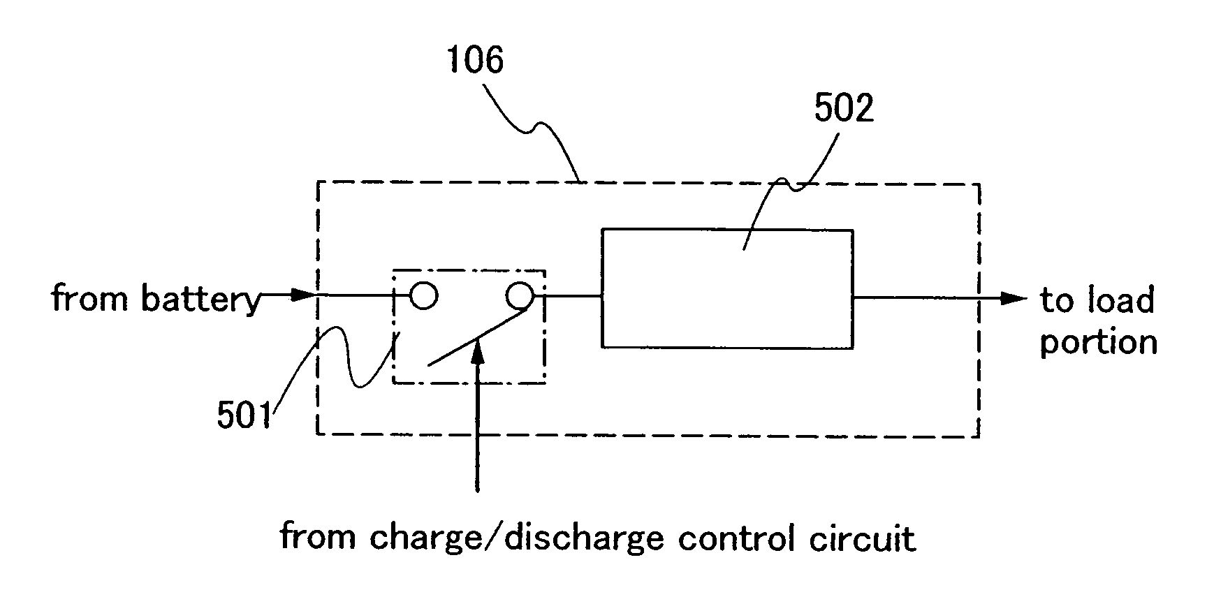
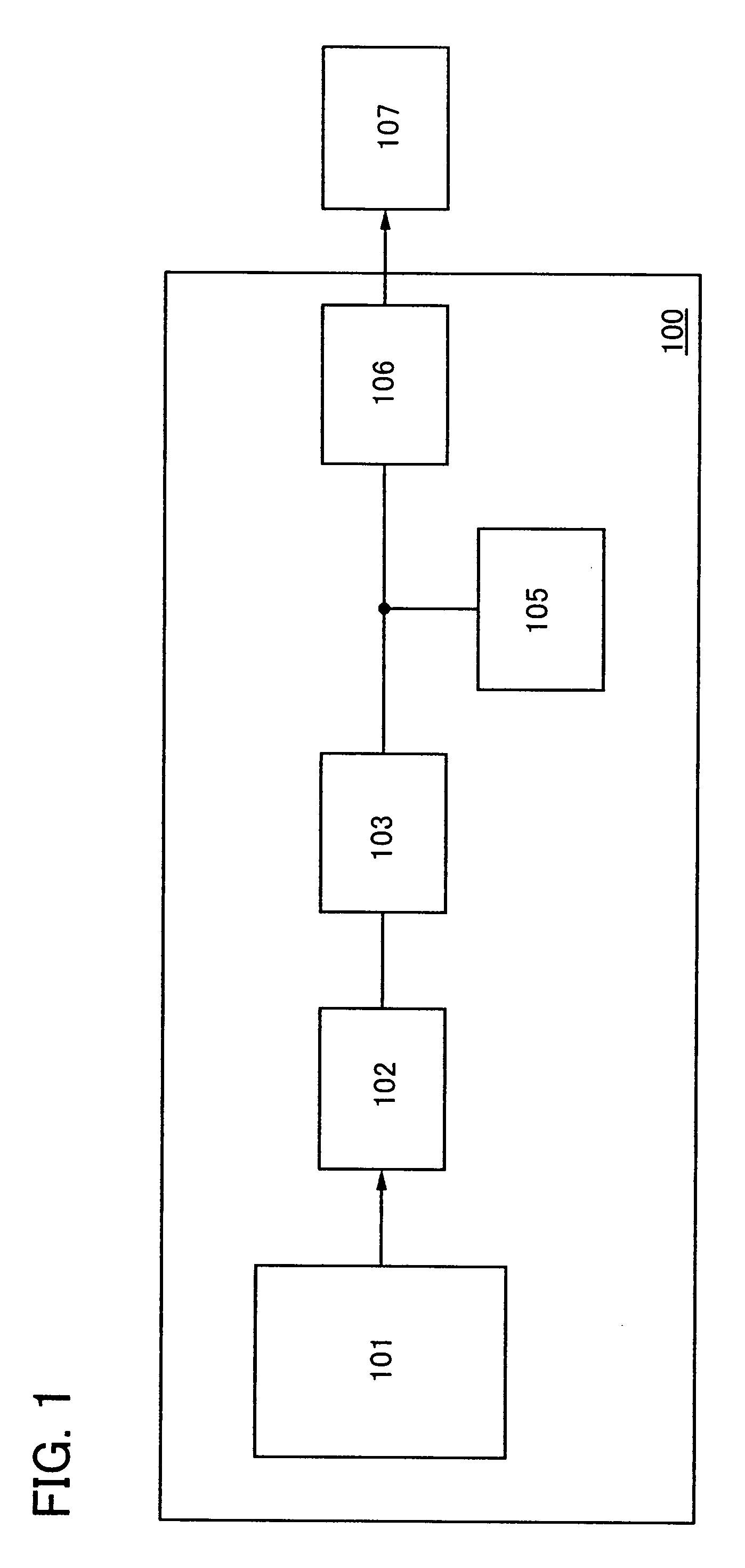
[0048]A wireless power storage device 100 described in this embodiment mode includes an antenna circuit 101, a rectifier circuit 102, a charge control circuit 103, a battery 105, and a discharge control circuit 106 (refer to FIG. 1). In the wireless power storage device 100, the battery 105 is charged when an electromagnetic wave is received by the antenna circuit 101 and the received electromagnetic wave is input to the battery 105 via the rectifier circuit 102. Further, the battery 105 is discharged when electrical power charged to the battery 105 is supplied to a load portion 107. The load portion 107 is provided with a circuit or the like which uses electrical power of the battery 105 to operate. Further, a structure in which the wireless power storage device 100 is provided with the load portion 107 can also be employed. Note that a stru...

embodiment mode 2

[0072]In this embodiment mode, a structure which differs from the structure of the wireless power storage device described in the previous embodiment mode will be described with reference to the drawings.

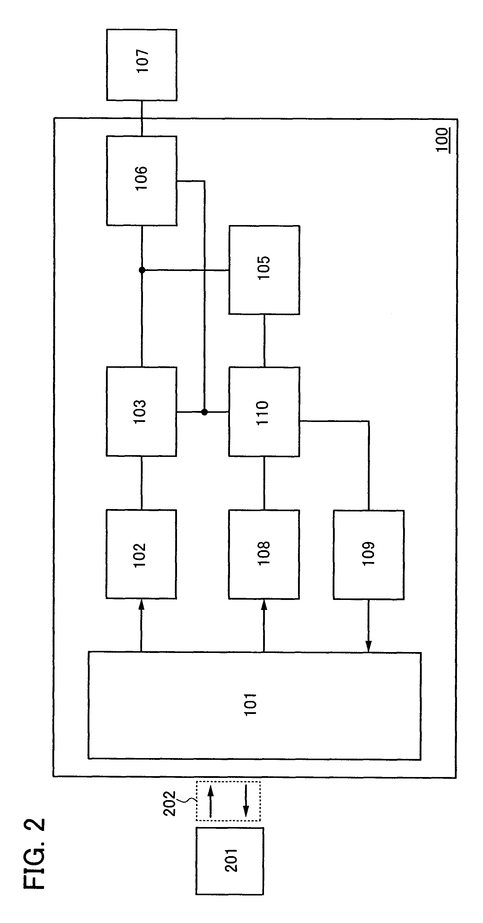
[0073]The wireless power storage device 100 described in this embodiment mode includes the antenna circuit 101, the rectifier circuit 102, the charge control circuit 103, the battery 105, the discharge control circuit 106, a demodulation circuit 108, a modulation circuit 109, and a charge / discharge control circuit 110 (refer to FIG. 2). In the wireless power storage device 100, when an electromagnetic wave is received from outside by the antenna circuit 101 and the received electromagnetic wave is input to the battery 105 via the rectifier circuit 102, the battery 105 is charged. Further, when electrical power charged to the battery 105 is supplied to the load portion 107, the battery 105 is discharged. Note that the wireless power storage device described in this embodiment mode ha...

embodiment mode 3

[0091]In this embodiment mode, an example of a semiconductor device which includes a wireless power storage device described in either of the previous embodiment modes (a semiconductor device provided with a signal processing circuit as a load) will be described with reference to the drawings. Specifically, an RFID (radio frequency identification) tag (also referred to as an IC (integrated circuit) tag, an IC chip, an RF tag, a wireless tag, a wireless chip, and an electronic tag) will be described as an example of a semiconductor device which communicates data via wireless communication. Note that the structure described in this embodiment mode is not limited to an RFID tag, and can be applied to any semiconductor device which communicates data via wireless communication (e.g., an electronic device which includes a battery).

[0092]An example of a semiconductor device described in this embodiment mode will be described with reference to FIG. 10.

[0093]A semiconductor device 150 shown ...


PUM

PropertyMeasurementUnit
voltageaaaaaaaaaa
voltageaaaaaaaaaa
frequencyaaaaaaaaaa

Abstract

To simplify charging of a battery in a power storage device which includes the battery. Further, to provide a wireless power storage device which can transmit and receive information without the task of replacing a battery for drive power supply, which becomes necessary when the battery depletes over time, being performed. An antenna circuit, a battery which is electrically connected to the antenna circuit via a rectifier circuit, and a load portion which is electrically connected to the battery are provided. The battery is charged when an electromagnetic wave received by the antenna circuit is input to the battery via the rectifier circuit, and discharged when electrical power which has been charged is supplied to the load portion. The battery is charged cumulatively, and the battery is discharged in pulses.

Description

BACKGROUND OF THE INVENTION[0001]1. Field of the Invention[0002]The present invention relates to a wireless power storage device and a semiconductor device including the wireless power storage device. In particular, the invention relates to a wireless power storage device which transmits and receives data through electromagnetic waves and receives electrical power through electromagnetic waves, and to a semiconductor device including the same.[0003]2. Description of the Related Art[0004]In recent years, various electric appliances are coming into wide use, and a wide variety of products are being put on the market. In particular, the spread of portable wireless communication devices has been notable. As a power supply for driving a portable wireless communication device, a battery, which is a power receiving means, is built-in, and power is obtained from the battery. As a battery, a secondary cell such as a lithium ion battery or the like is used. As matters now stand, the battery i...

Claims


Application Information

Patent Timeline
Patent Type & Authority Patents(United States)
IPC IPC(8): H01M10/44H01M10/46
CPCG06K19/0702G06K19/0707G06K19/0723H01M10/425H01M10/44H01M10/46H01M10/48H02J17/00H01M6/40H02J50/20Y02E60/10H02J50/402H02J50/005
Inventor YAMAZAKI, SHUNPEIOSADA, TAKESHI
Owner SEMICON ENERGY LAB CO LTD
Why Eureka
Try Eureka