Light branching optical waveguide

a branching optical waveguide and light branching technology, applied in the field of light branching optical waveguides, can solve the problems of large branch loss, limited radius of curvature increase, and point cannot be of a completely sharp structure, so as to reduce the variation of branching ratio, reduce the branch loss, and reduce the wavelength dependence

Inactive Publication Date: 2010-11-23
RESONAC CORPORATION
View PDF8 Cites 10 Cited by
  • Summary
  • Abstract
  • Description
  • Claims
  • Application Information

AI Technical Summary

Benefits of technology

[0016]The present invention has been made in view of the above problems, and an object of the present invention is to provide a low-loss light branching optical waveguide having a reduced branch loss and a reduced variation in branching ratio. Another object of the present invention is to provide a light branching optical waveguide having small wavelength dependence as well as a reduced branch loss and a reduced variation in branching ratio.
[0017]The inventors of the present invention have found that a branch loss and a variation in branching ratio can be reduced by shifting the geometrical central axis of an incident light waveguide and the geometrical central axis of a multi-mode optical waveguide and / or by making the core shape of the multi-mode optical waveguide asymmetric with respect to the geometrical central axis of the waveguide even when the intensity distribution (field distribution) of light propagating in an optical waveguide on an incident side is asymmetric with respect to the geometrical central axis of the optical waveguide.
[0018]Furthermore, they have found that a branch loss and a variation in branching ratio can be suppressed irrespective of a wavelength by matching the wavelength dependence of a field distribution generated by shifting the geometrical central axis of an incident light waveguide and the geometrical central axis of a multi-mode optical waveguide to the wavelength dependence of a field distribution generated by making the core shape of the multi-mode optical waveguide asymmetric with respect to the geometrical central axis of the waveguide. The present invention has been completed by this finding.
[0031]According to the present invention, there can be provided a low-loss light branching optical waveguide having a reduced branch loss and a reduced variation in branching ratio. In addition, there can be provided a light branching optical waveguide having small wavelength dependence as well as a reduced branch loss and a reduced variation in branching ratio.

Problems solved by technology

In actuality, the size of the circuit is restricted by the size of a substrate, so an increase in radius of curvature is limited.
However, the point cannot be of a completely sharp structure owing to, for example, the accuracy of patterning or etching.
An optical central portion having the highest light intensity (the central axis of an optical propagation mode) is scattered at the branch point 5, thereby causing a large branch loss.
In each of those cases, there arises a problem in that the branching ratio of the light branching optical waveguide cannot be equal even when such offset structure as described above is arranged.
On the other hand, when light propagating in an incident light waveguide has an intensity distribution (field distribution) of light asymmetric with respect to the geometrical central axis of the incident light waveguide, making the shape of the distribution symmetric requires a long straight line portion, so there arises a problem in that the size of a module increases.
That is, for example, in the case where the intensity distribution (field distribution) of light propagating in an optical waveguide on an incident side is asymmetric with respect to the geometrical central axis of the optical waveguide, there arises a problem in that the branching ratio of light cannot be equal even in an MMI type light branching optical waveguide.
Therefore, there arises a problem in that each of a loss of light intensity and a branching ratio is dependent on the wavelength.
That is, the design of the MMI type light branching optical waveguide must be changed in accordance with the wavelength of light, so there arises a problem such as a reduction in efficiency of production.Patent Document 1: JP 04-213407 APatent Document 2: JP 2000-121857 A

Method used


Image

  • Light branching optical waveguide
  • Light branching optical waveguide
  • Light branching optical waveguide

Examples


example 1

[0097]A light branching optical waveguide having a sketchy structure shown in FIG. 10 was produced by means of the following materials.[0098]Core: Fluorinated polyimide resin (“OPI-N3205” manufactured by Hitachi Chemical Co., Ltd.)[0099]Clad: Fluorinated polyimide resin (“OPI-N1005” manufactured by Hitachi Chemical Co., Ltd.)

[0100]The incident light waveguide (single mode, core portion) 7, and the two output light waveguides (single mode, core portions) 8 and 9 each had a width w1 of 6.5 μm, the multi-mode optical waveguide had a width w2 of 15 μm and a length L of 220 μm, and a distance d between the output light waveguides (single mode, core portions) at the exit of the multi-mode optical waveguide was 3.5 μm. The incident light waveguide (core portion) 7 had a curve portion with a radius r of curvature as 15 mm, as shown in FIG. 10. The intensity distribution of light entering into the multi-mode optical waveguide from the incident light waveguide at the connecting surface 10 of ...

example 2

[0102]A light branching optical waveguide having a multi-mode optical waveguide with a core shape having such a notch as shown in FIG. 11 was produced by means of the same materials as those shown in Example 1.

[0103]The incident light waveguide (core portion) 7, and the two output light waveguides (core portions) 8 and 9 each had a width w1 of 6.5 μm, the multi-mode optical waveguide had a width w2 of 15 μm and a length L of 220 μm, and a distance d between the output light waveguides at the exit of the multi-mode optical waveguide was 3.5 μm. The geometrical central axis a of the incident light waveguide (core portion) 7 and the geometrical central axis b of the multi-mode optical waveguide were allowed to coincide with each other. The entrance portion of the multi-mode optical waveguide was cut from a side edge by a distance z (z=0.6 μm). That is, the multi-mode optical waveguide had a sinusoidal curve structure ranging from its entrance portion to its exit portion. Although not s...

example 3

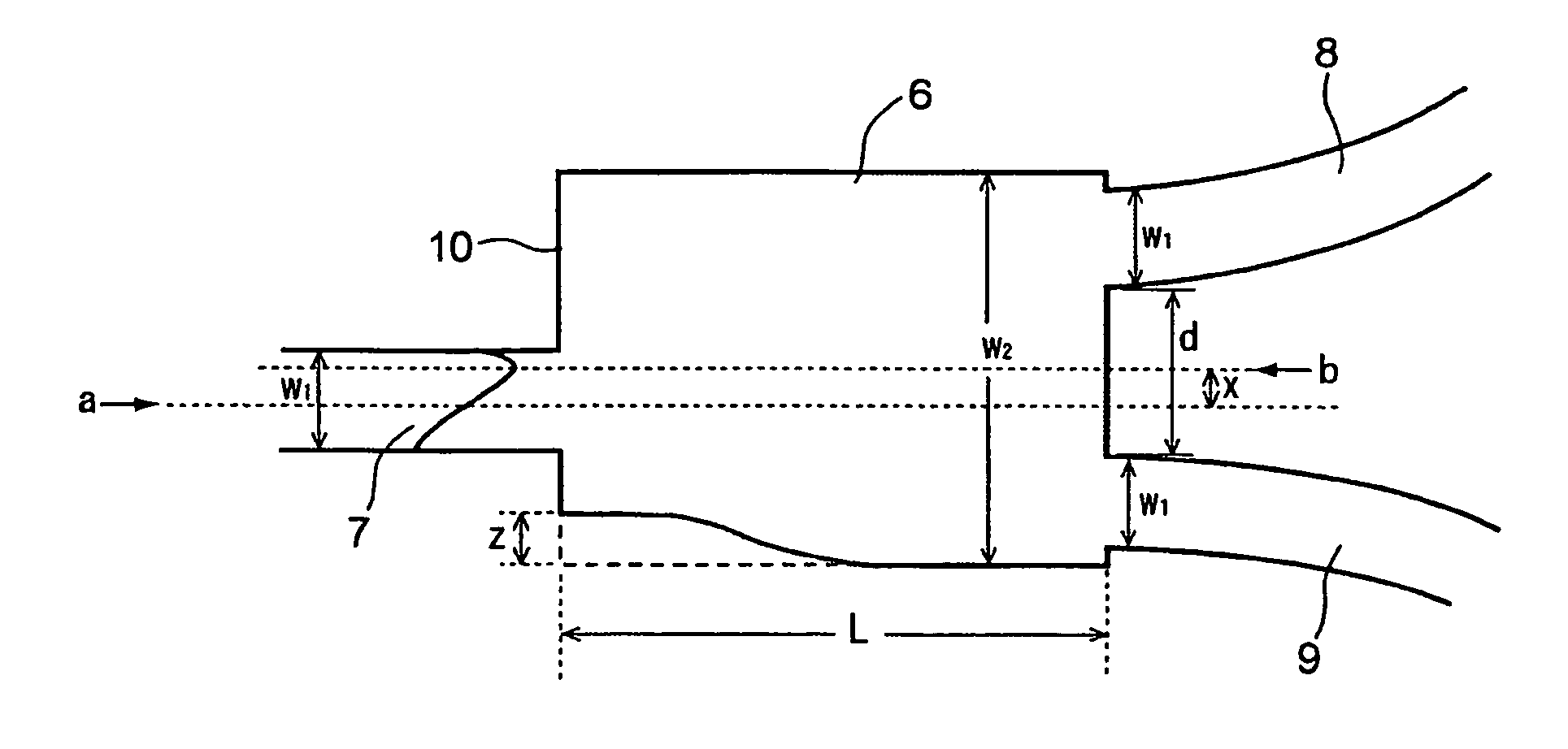
[0104]A light branching optical waveguide having the core shape of a multi-mode optical waveguide having such a notch as shown in FIG. 12 and an offset structure was produced by means of the same materials as those shown in Example 1.

[0105]The incident light waveguide (core portion) 7, and the two output light waveguides (core portions) 8 and 9 each had a width w1 of 6.5 μm, the multi-mode optical waveguide had a width w2 of 15 μm and a length L of 220 μm, and a distance d between the output light waveguides at the exit of the multi-mode optical waveguide was 3.5 μm. The entrance portion of the multi-mode optical waveguide was cut from a side edge by a distance z (z=0.8 μm). That is, the multi-mode optical waveguide had a sinusoidal curve structure ranging from its entrance portion to its exit portion. The offset x between the geometrical central axis a of the incident light waveguide (core portion) 7 and the geometrical central axis b of the multi-mode optical waveguide was 0.9 μm....


PUM


Abstract

Provided is a light branching optical waveguide including: at least one incident light waveguide (A) optically connected to one end of a multi-mode optical waveguide; and output light waveguides (B) larger in number than the incident light waveguide (A) optically connected to the other end thereof, the light branching optical waveguide being characterized in that: an intensity distribution of light incident from at least one optical waveguide (a) out of the incident light waveguide (A) on the multi-mode optical waveguide at a connecting surface of the incident light waveguide (A) and the multi-mode optical waveguide is asymmetric with respect to a geometrical central axis of the optical waveguide (a); and an extended line of the geometrical center axis of the optical waveguide (a) does not coincide with a geometrical central axis of the multi-mode optical waveguide. Accordingly, it is possible to obtain a low-loss light branching optical waveguide having a reduced branch loss and a reduced variation in branching ratio, and further to obtain a light branching optical waveguide having small wavelength dependence as well as a reduced branch loss and a reduced variation in branching ratio.

Description

TECHNICAL FIELD[0001]The present invention relates to a light branching optical waveguide and an optical device using the same.BACKGROUND ART[0002]There has been an abruptly growing demand on information transmission in association with the recent widespread use of personal computers and the Internet, so optical transmission with a high transmission rate has become widespread. An optical waveguide has been used as an optical interconnection in such optical transmission.[0003]By the way, an optical branching circuit and an optical multiplexing circuit serving as basic elements are indispensable to an integrated optical circuit, and an optical waveguide branched to provide a Y shape has been conventionally known. As shown in FIG. 1, a conventional Y branch optical waveguide is structured by connecting a main waveguide 1, a taper waveguide 2, and branching waveguides 3 and 4, and a branch point 5 is present between the taper waveguide 2 and the branching waveguides 3 and 4.[0004]A redu...

Claims


Application Information

Patent Timeline
Patent Type & Authority Patents(United States)
IPC IPC(8): G02B6/26G02B6/42G02B6/122G02B6/28
CPCG02B6/2813
Inventor MIYADERA, NOBUOYAMAMOTO, REI
Owner RESONAC CORPORATION
Why Eureka
Try Eureka