
Pneumatic proportioning system for vehicle air springs

a pneumatic proportioning and axle/suspension technology, which is applied in the direction of valve operating means/release devices, shock absorbers, transportation items, etc., can solve the problems of relative rough ride to cargo and/or passengers, and premature failure of front and rear axle/suspension systems and their associated components, such as the axl

Active Publication Date: 2010-11-30
HENDRICKSON USA L L C
View PDF42 Cites 23 Cited by
  • Summary
  • Abstract
  • Description
  • Claims
  • Application Information

AI Technical Summary

Benefits of technology

The pneumatic proportioning system reduces the likelihood of premature failure of suspension components, maintains optimal vehicle height, and increases lateral steer compliance, leading to extended component life and reduced operating costs.

Problems solved by technology

Early suspension designs included heavy leaf spring suspensions which resulted in a relatively rough ride to the cargo and / or passengers carried by the vehicle, and did not allow loads to equalize among the axles in all situations, thus creating the need for an axle / suspension system with softer ride characteristics and more efficient equalization characteristics.
Typically, these prior art pneumatic control systems exhaust all of the air from the air springs of the rear axle / suspension system.
This effective shortening of the longitudinal wheel base of the heavy-duty vehicle as a result of complete exhaustion of the air springs of the rear axle / suspension system increases maneuverability of the vehicle, but may lead to premature failure of certain components of the front and rear axle / suspension systems.
Problems which can typically occur in these prior art pneumatic control systems that exhaust all of the air from the air springs of the rear axle / suspension system include: 1) overloading of the front axle / suspension system and its associated components; 2) contact between the jounce stop or bumper of the air spring and the upper bead plate of the air spring in both the front and rear axle / suspension systems; and 3) trapping of the exhausted air springs of the rear axle / suspension system.
More particularly, when the air is exhausted as described above in a vehicle which is heavily loaded, the front axle / suspension system to which the cargo loads are effectively transferred can become overloaded, which can lead to premature failure of the front axle / suspension system and its associated components, such as the axle, the suspension assemblies, the air springs, the wheel end assemblies, and the tires.
Also, when the air is exhausted as described above in a vehicle which is heavily loaded, the front axle / suspension system to which the cargo loads are effectively transferred is often unable to maintain vehicle ride height.
More specifically, the loads that are transferred to the front axle / suspension system may require a pressure in the air springs that far exceeds the available system pressure.
Such uncontrolled load transfer can exceed the maximum design strength of the air spring jounce stop and the suspension assembly components, possibly causing these components to fail prematurely.
In addition, when the jounce stop or bumper in each air spring of the axle / suspension system contacts the upper bead plate, the friction between the jounce stop or bumper and the upper bead plate may greatly reduce the ability of the suspension assemblies to move in a horizontal plane.
Increased lateral forces acting through the suspension assemblies also increase the probability of premature failure of the components of the suspension assemblies.
Yet another common issue which is prevalent in current prior art pneumatic control systems is the tendency for the flexible air spring member of the exhausted air spring to pinch or become trapped at the top of the air spring piston.
This trapping of the flexible air spring member can increase the probability of premature failure of the air spring.
More specifically, the flexible member of the air spring becomes trapped between the internal jounce stop and the upper bead plate of the air spring which can cause damage to the flexible member.
Such overloading and undesirable contact can cause the air springs and the suspension assembly components of an axle / suspension system to exceed maximum design strength and increases the probability of premature failure of the axle / suspension systems and their associated components, in addition to decreasing lateral steer compliance of the suspension assemblies which can increase the probability of premature failure of the components.

Method used


Image

  • Pneumatic proportioning system for vehicle air springs
  • Pneumatic proportioning system for vehicle air springs
  • Pneumatic proportioning system for vehicle air springs

Examples


Embodiment Construction

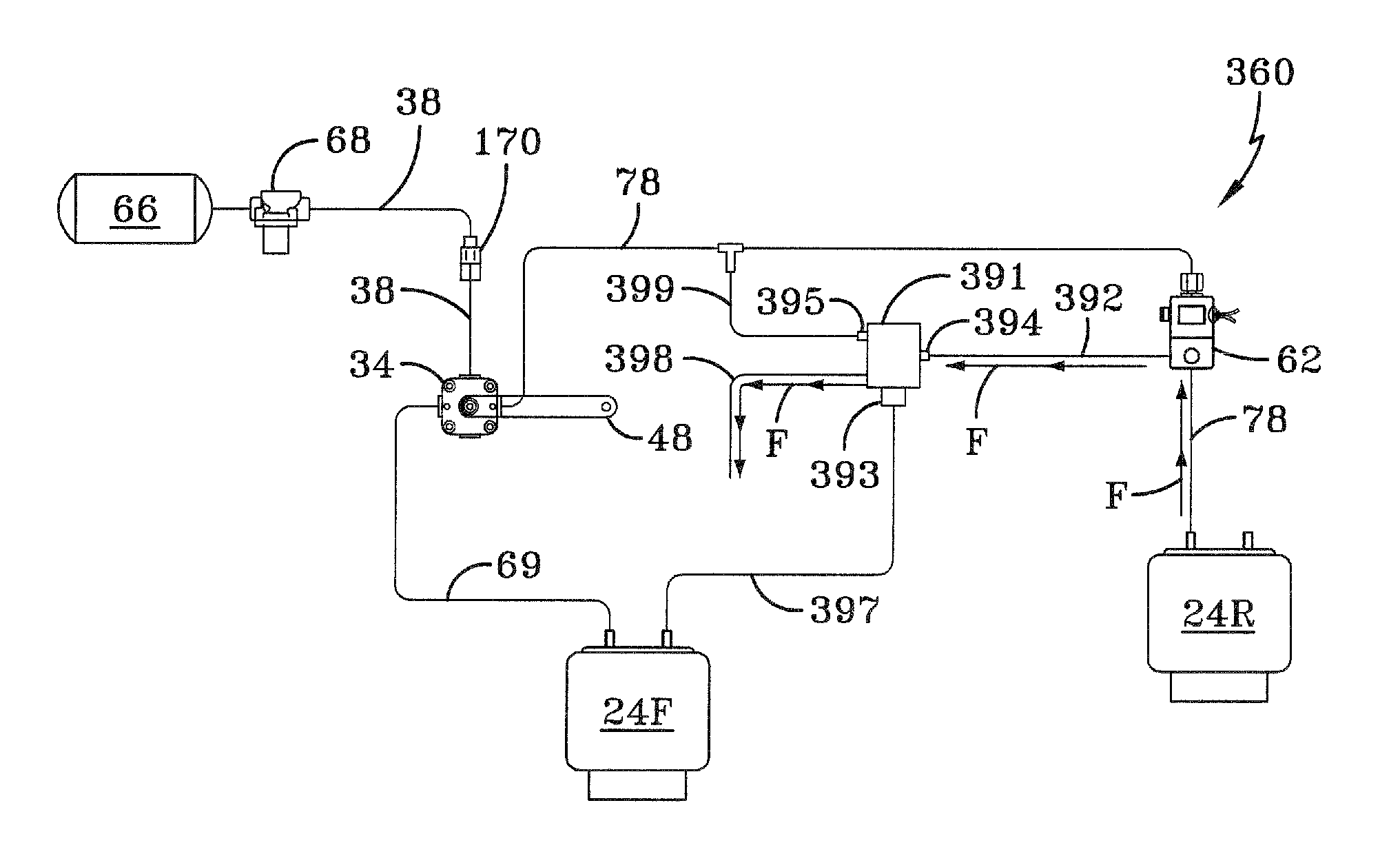
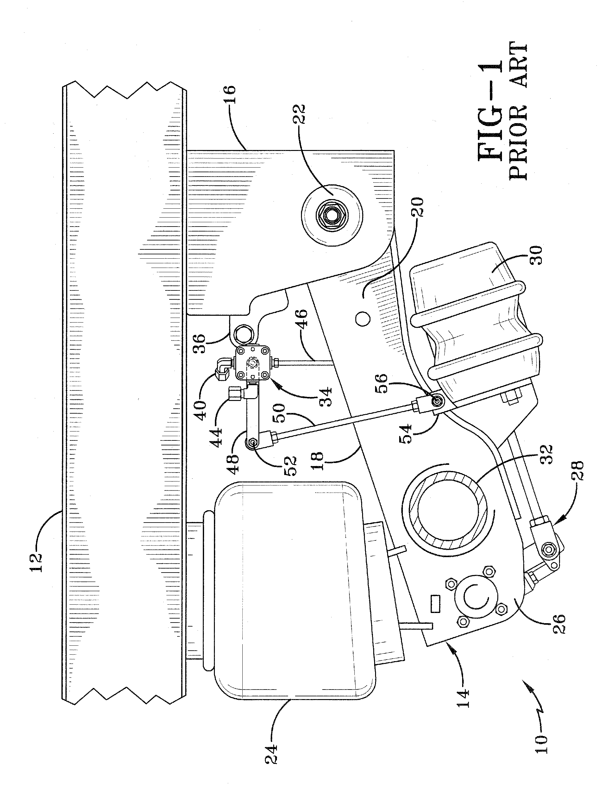
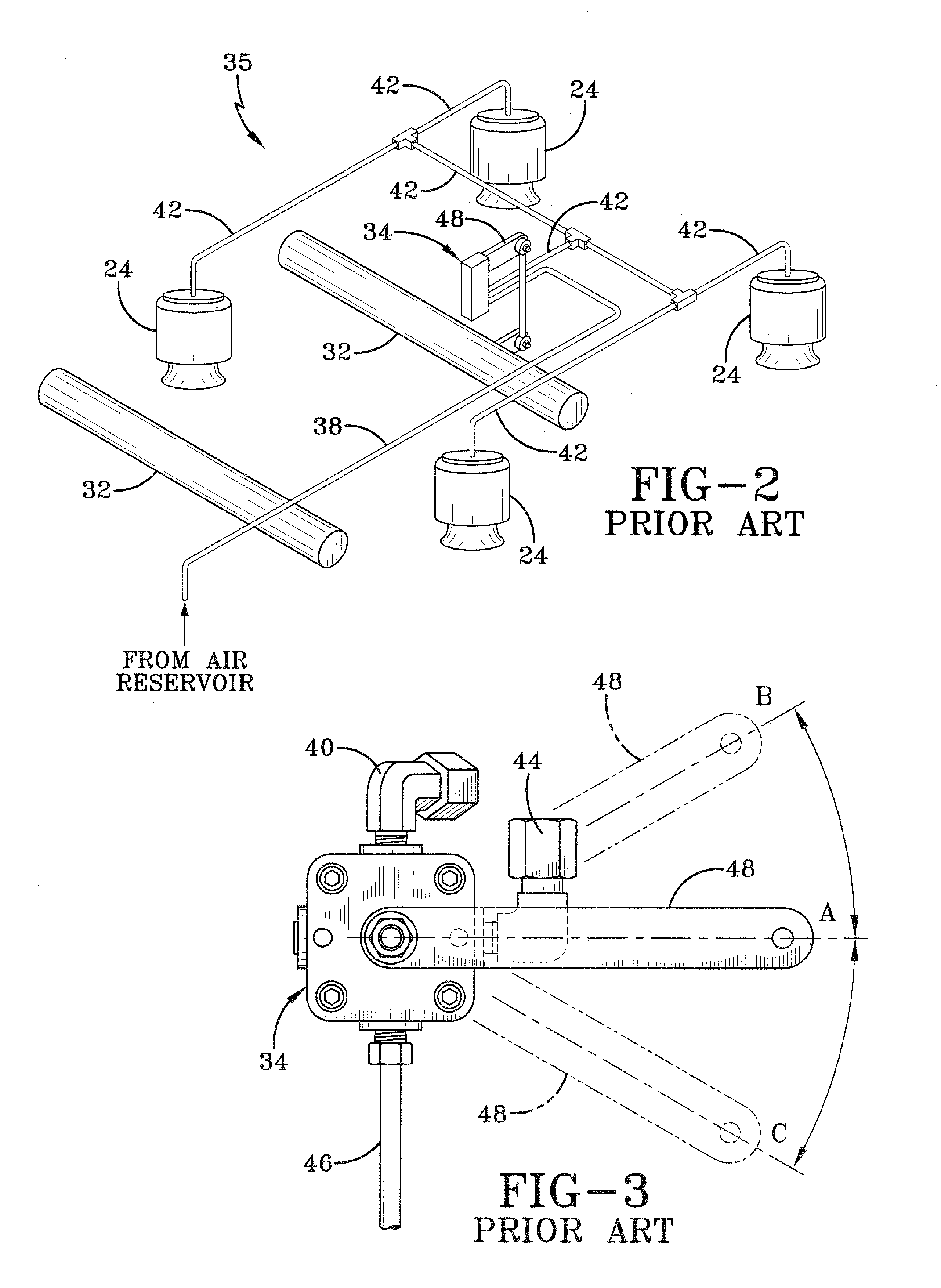
[0041]So that the structure, operation, and advantages of the pneumatic proportioning system for air springs of an air-ride axle / suspension system of a heavy-duty vehicle of the present invention can be best understood, a typical prior art pneumatic control system will now be described in the environment in which it is utilized. It is important to note that prior art air-ride axle / suspension system 10, while shown as a beam-type trailing arm axle / suspension system, also includes other types of heavy-duty vehicle air-ride axle / suspension systems known to those skilled in the art, such as leading arm beam-type air-ride axle / suspension systems and air-ride axle / suspension systems other than beam-type. It is also important to note that vehicle frame 12 is generally representative of various types of frames commonly used for heavy-duty vehicles, including primary frames that do not support a subframe, primary frames and / or floor structures that do support a subframe, and subframes themse...


PUM


Abstract

A pneumatic proportioning system for heavy-duty vehicle air springs includes an air supply, a height control valve and a solenoid valve in fluid communication with one another and with the air springs of at least one axle / suspension systems of a heavy-duty vehicle. A proportioning means is in fluid communication with the air supply, with the height control valve, with the solenoid valve, with the air springs and with atmosphere and operates to proportion loads between the air springs of the axle / suspension systems when the solenoid valve is activated during operation of the heavy-duty vehicle.

Description

[0001]This application claims the benefit of U.S. Provisional Application No. 60 / 952,951, filed on Jul. 31, 2007.BACKGROUND OF THE INVENTION[0002]1. Field of the Invention[0003]The invention relates generally to the art of air-ride axle / suspension systems for heavy-duty vehicles, such as tractor-trailers or semi-trailers, which cushion the ride and stabilize the vehicle during operation. More specifically, the invention relates to control of the air springs of an air-ride axle / suspension system, and in particular to a pneumatic proportioning system which regulates and proportions air among air springs of an air-ride axle / suspension system.[0004]2. Background Art[0005]Heavy-duty vehicles, such as tractor-trailers or semi-trailers, typically include two or more leading or trailing arm suspension assemblies that connect the wheel-bearing axles of the vehicle to the frame of the vehicle. Early suspension designs included heavy leaf spring suspensions which resulted in a relatively rough...

Claims


Application Information

Patent Timeline
Patent Type & Authority Patents(United States)
IPC IPC(8): B60G11/26
CPCB60G17/0155B60G17/0523B60G17/0526B60G2202/152B60G2300/026B60G2300/0262B60G2300/042B60G2400/252B60G2400/51222B60G2400/61B60G2500/202B60G2500/2021B60G2500/203B60G2500/204B60G2500/30B60G2600/20B60G2600/26B60G2800/915Y10T137/7837Y10T137/7761
Inventor MORRIS, BRIAN R.CERVANTEZ, JESSE W.PADULA, SANTOOYSTER, MICHAEL D.
Owner HENDRICKSON USA L L C
Features
  • Generate Ideas
  • Intellectual Property
  • Life Sciences
  • Materials
  • Tech Scout
  • Unparalleled Data Quality
  • Higher Quality Content
  • 60% Fewer Hallucinations
Learn More