Device for connecting a camera to a supporting device

a technology for supporting devices and cameras, which is applied in the direction of dovetail-like connections, large fixed members, and television systems, etc., can solve the problems of blurred photos, manual force applied to the locking plate to the camera, and inability to secure in any way, so as to achieve high compressive force, low operating force, and high compressive force

Active Publication Date: 2010-11-30
ARNOLD & RICHTER CINE TECHN & BETRIEBS
View PDF11 Cites 9 Cited by
  • Summary
  • Abstract
  • Description
  • Claims
  • Application Information

AI Technical Summary

Benefits of technology

[0021]This straight forward mechanical configuration of the rear clamping mechanism ensures that, when the operating lever is opened, the securing pin is driven upwards via the threaded drive and thus releases the guide shoe, which is connected to the camera, whereas, when the operating lever is moved in the opposite direction, the securing pin is drawn downwards, i.e. in the direction of the locking plate, and, in the process, arrests the guide shoe between an end collar of the securing pin and the plane of the locking plate.
[0022]In order to compensate for thickness tolerances of

Problems solved by technology

Despite large cross sections and constants of the compression springs, it is impossible to avoid the situation, in the case of the known quick-clamping locking plate, where, as a result of the long lever arm between the quick-clamping locking plate and the opposite, top end of the camera, the camera can execute undesirable movements which result in the photographs being blurred.
Furthermore, locking of the quick-clamping locking plate to the camera requires a high level of manual force to be applied upon adjustment of the front and rear pressure plates.
A further disadvantage of the known locking plat

Method used


Image

  • Device for connecting a camera to a supporting device
  • Device for connecting a camera to a supporting device
  • Device for connecting a camera to a supporting device

Examples


Embodiment Construction

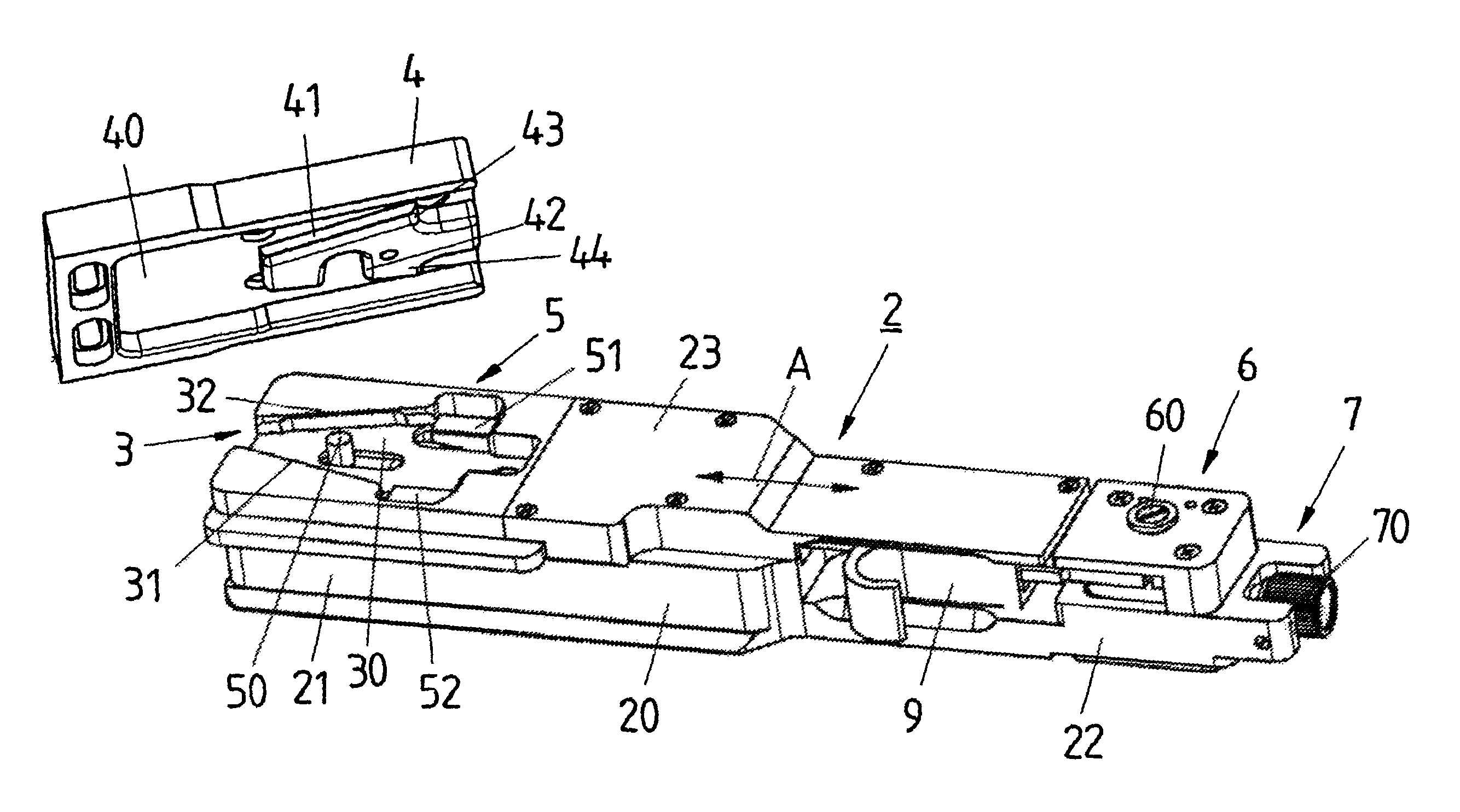
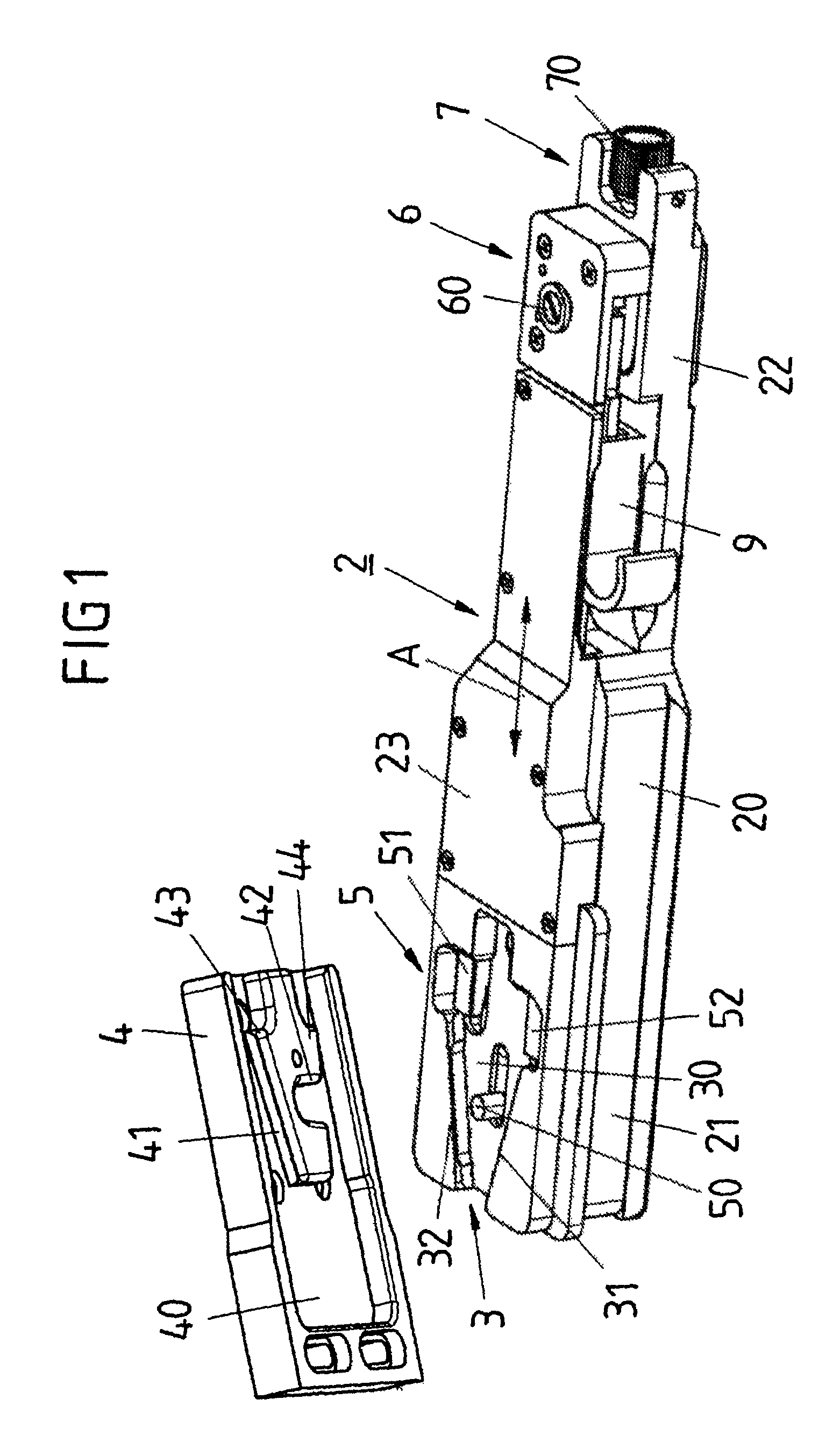
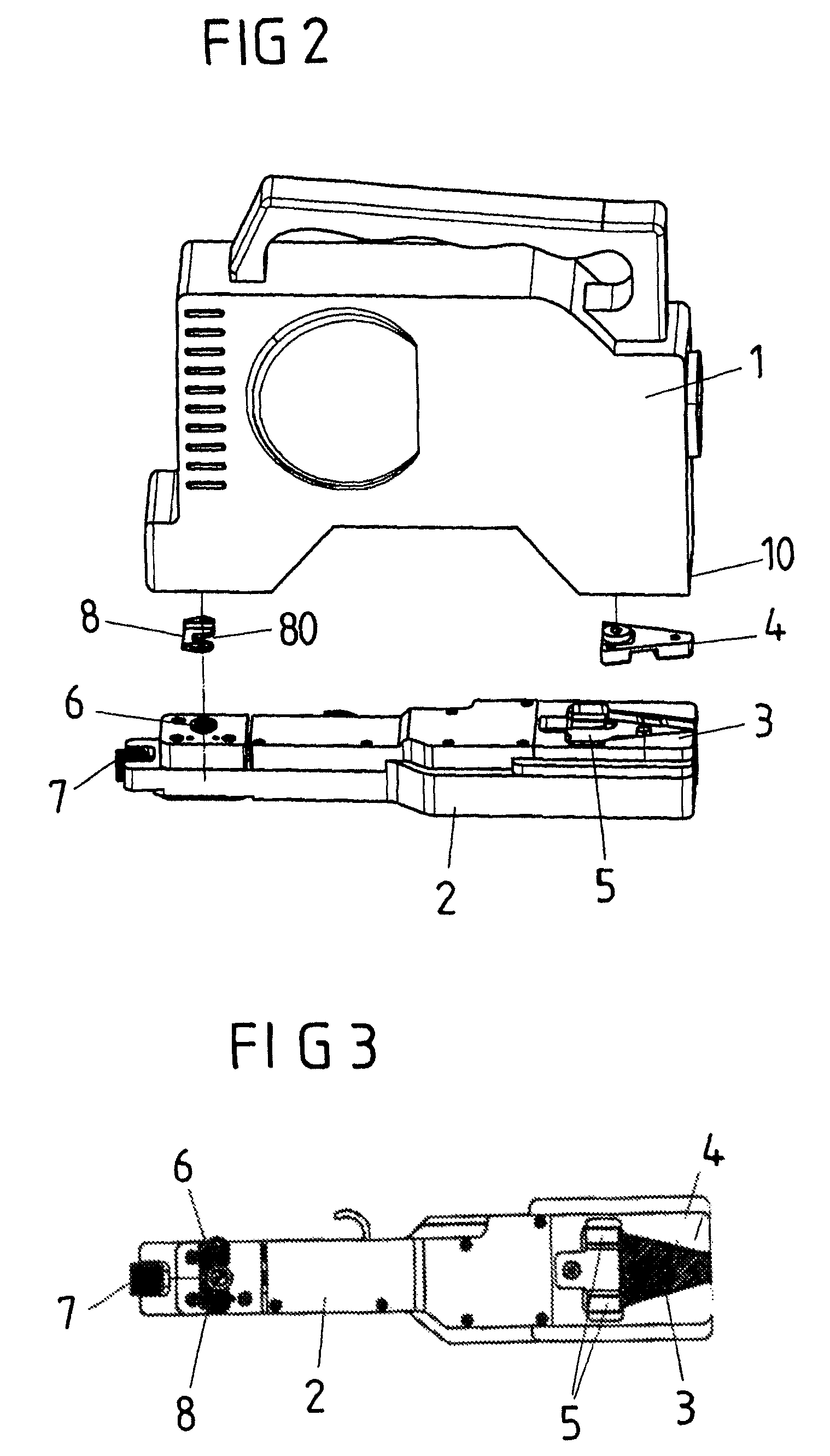
[0033]The locking plate 2 contains a base plate 20 and a cover plate 23 and, according to FIG. 4, has, at the bottom of the base plate 20, a slotted box profile 24 by means of which the locking plate 2 can be plugged onto a corresponding mating profile of a supporting device, for example a camera stand, and can be connected in a positive-closing manner to this supporting device. The design and functioning of the locking plate 2 make is possible for a camera to be quickly and easily positioned on the locking plate 2, clamped into the locking plate 2 and locked to the locking plate 2 and disengaged from the locking plate 2.

[0034]In its front region 21, the locking plate 2 has a wedge-shaped recess 3, of which the base 30 is bounded by two guides 31, 32 with inclined walls for forming a dovetail guide, these approaching one another conically in relation to the longitudinal axis A which runs from the front region 21 to the rear region 22 of the locking plate 2. The wedge-shaped recess 3...


PUM


Abstract

A device for connecting a camera to a supporting device as provided. The device has a locking plate which includes a wedge-shaped recess with a dovetail guide which is insertable into a wedge-shaped plate with another dovetail guide. The wedge-shaped plate is connectible to the camera. The device also has a front clamping mechanism for bracing the wedge-shaped plate in the wedge-shaped recess, and in a rear region, has a rear clamp mechanism with a securing pin for engaging a guide shoe connectible to the camera. The device also includes a setting device for adjusting the front clamping mechanism along a longitudinal axis of the locking plate.

Description

CROSS-REFERENCE TO RELATED APPLICATION[0001]This application claims priority of German Patent Application Number 20 2007 012 388.4, filed on Sep. 3, 2007.BACKGROUND OF THE INVENTION[0002]The invention relates to a device for connecting a camera to a supporting device.[0003]U.S. Pat. No. 5,870,641 A1 discloses a quick-clamping locking plate for a camera which is positioned on a camera stand and so as to make it possible for a camera to be quickly clamped in, locked and disengaged. The quick-clamping locking plate has, in its front region, a dovetail guide, of which the guide edges approach one another conically in the direction of the front end of the plate and serve for accommodating a complementary insert part which is connected to the camera. The insert part, which is pushed into the dovetail guide, is arrested with the aid of a clamping pin which can be displaced along the centre longitudinal axis of the plate and is connected to a pivotable hand lever via a linkage. A tightening...

Claims


Application Information

Patent Timeline
IPC IPC(8): G03B17/00F16M11/04
CPCG03B17/56Y10T403/7094F16B2200/30G03B17/566
Inventor ELIAS, JAMESSCHUSTER, DAVID
Owner ARNOLD & RICHTER CINE TECHN & BETRIEBS
Why Eureka
Try Eureka