
Pulsatile fluid delivery system

a technology of pulsatile and fluid, applied in electrotherapy, other medical devices, therapy, etc., can solve the problems of reducing the rate of oxygen consumption of the heart, reducing the tolerance of the myocardium for ischemia (reduction of blood supply), and immediate cardiac arres

Active Publication Date: 2010-11-30
QUEST MEDICAL
View PDF18 Cites 8 Cited by
  • Summary
  • Abstract
  • Description
  • Claims
  • Application Information

AI Technical Summary

Benefits of technology

"The present invention provides a system for delivering blood, cardioplegia solution, and other medications or fluids in a pulsatile flow to a patient during cardiopulmonary bypass. The system uses a dual chambered pumping apparatus or a single chambered pumping apparatus with a piston that can deliver fluid during a stroke while simultaneously filling the chamber on the opposite side of the piston. The system can achieve a desired average flow rate by adjusting the alternating velocities and a duty cycle for the flow rate alternation. The calculations necessary to obtain the desired average flow rate are performed by a microprocessor that also controls the movement of the pistons. The technical effects of the invention include improved delivery of fluids to a patient during cardiopulmonary bypass, reduced damage to the patient's body, and improved surgical outcomes."

Problems solved by technology

Indeed, the myocardium has a very low tolerance for ischemia (reduction in blood supply), due to its high oxygen requirements.
The potassium infusion causes an immediate cardiac arrest, while the typically low temperature of the solution reduces the heart's rate of oxygen consumption.
Since the heart is no longer available to maintain the patient's circulation, artificial pump means must be employed.
Both of these types of designs, however, are limited in their ability to produce a pulsatile flow of desired characteristics while still maintaining a desired average flow rate.

Method used


Image

  • Pulsatile fluid delivery system
  • Pulsatile fluid delivery system
  • Pulsatile fluid delivery system

Examples


Embodiment Construction

[0029]The following is intended to provide a detailed description of an example of the invention and should not be taken to be limiting of the invention itself. Rather, any number of variations may fall within the scope of the invention, which is defined in the claims following the description.

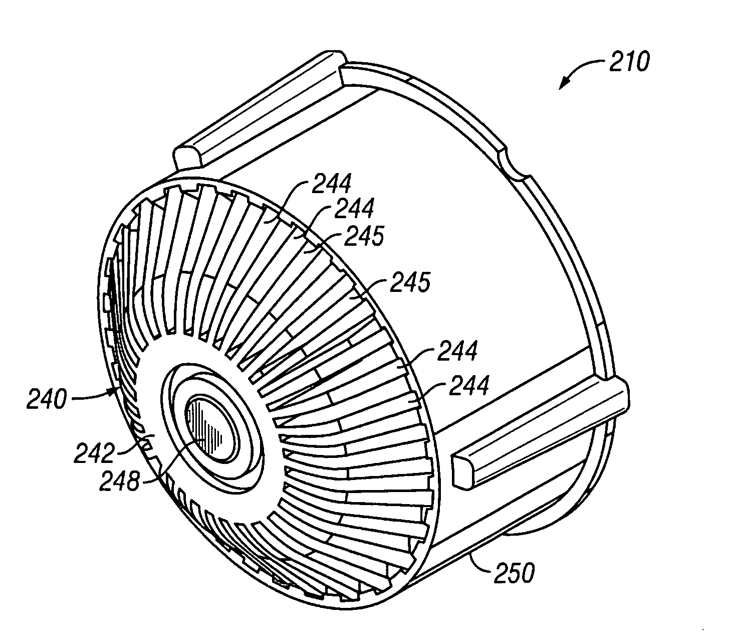
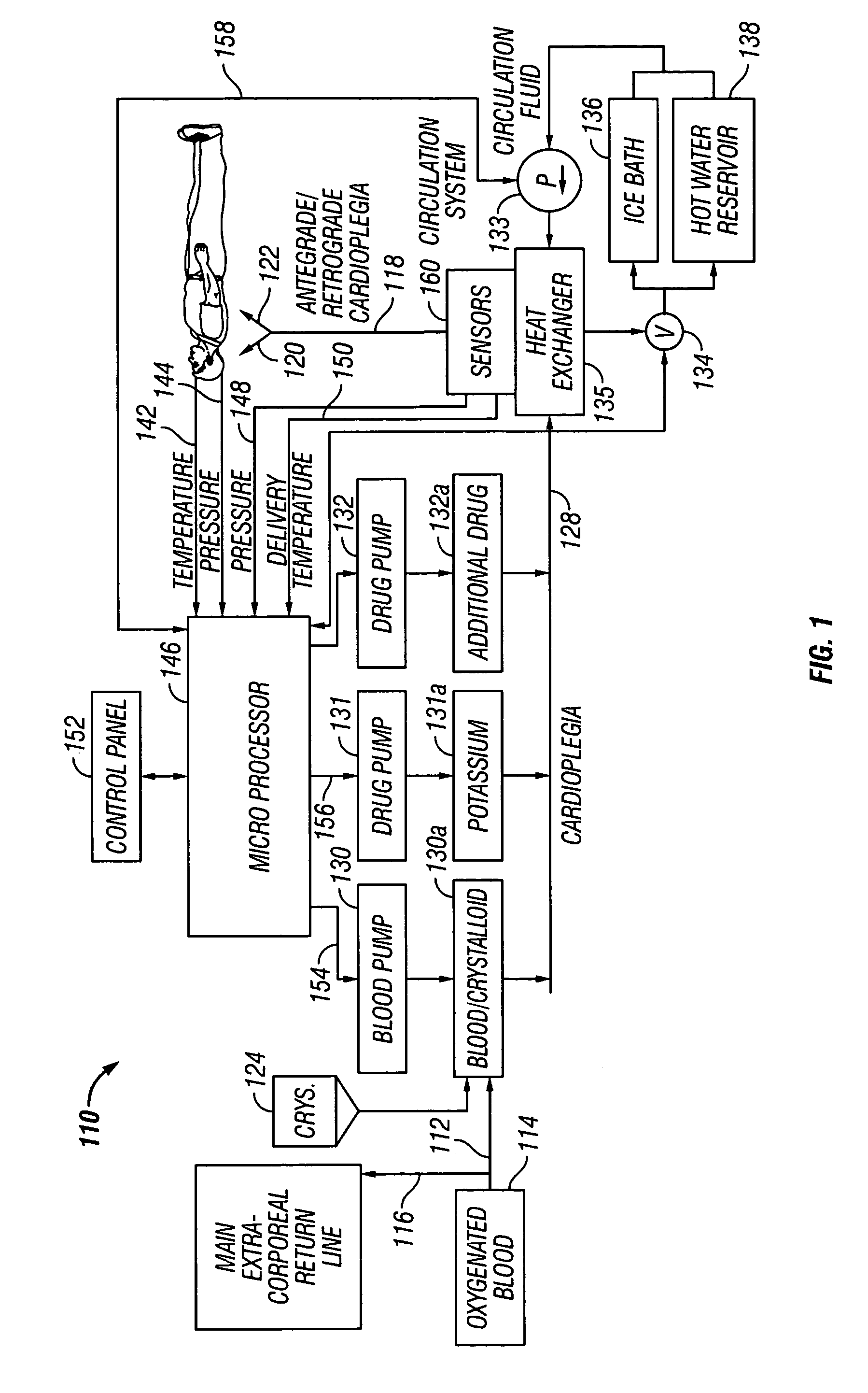
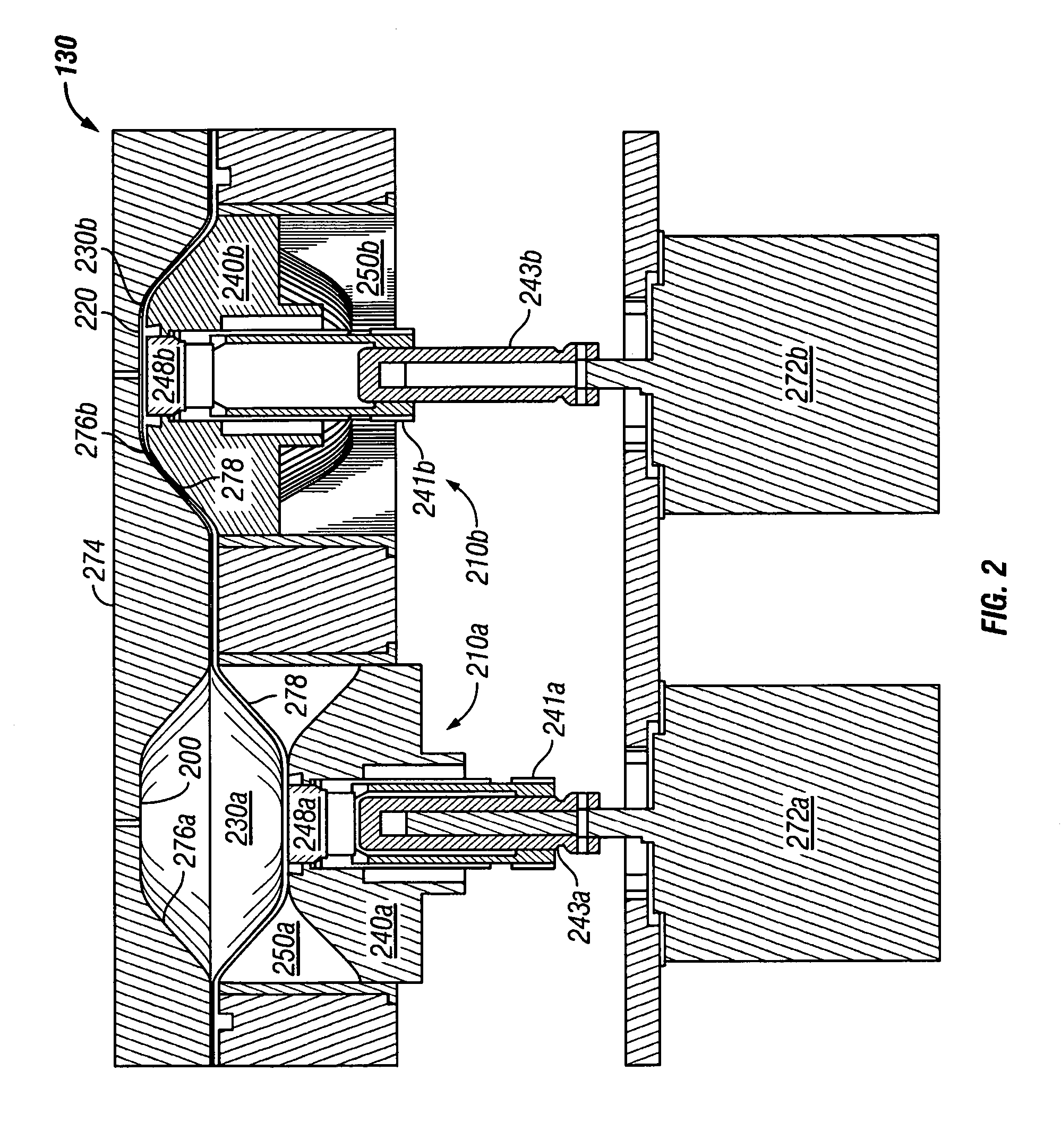
[0030]A preferred embodiment of the present invention is directed to a system for delivering a pulsatile flow of blood and crystalloid cardioplegia solution to a patient undergoing open-heart surgery. In particular, a preferred embodiment of the present invention allows a perfusionist or surgeon to select between two different delivery modes, one in which fluids are delivered to the patient in a pulsatile flow and another in which fluids are delivered to the patient in a nonpulsatile flow. The two different modes of operation are supported by software, which controls the mechanical operation of the pump. The electromechanical components utilized in both modes are the same, the only difference ...


PUM


Abstract

A system for delivering blood, cardioplegia solution, and other medications or fluids in a pulsatile flow pattern to a patient during cardiopulmonary bypass is disclosed. In a preferred embodiment, a pumping apparatus having at least one chamber is utilized in which a pumping action is achieved by compressing one of the chambers with a piston mechanism, while allowing the other chamber to fill with fluid via retracting its respective piston. The instantaneous flow rate of either of the chambers is determined by the speed of the piston. In a preferred embodiment, a pulsatile flow of fluid is achieved by cyclically alternating the velocity of the piston between two different speeds. A desired average flow rate and / or delivery pressure and / or constant pulse pressure is maintained by adjusting the alternating velocities at the desired frequency and duty cycle. The calculations necessary to obtain a desired average flow rate are performed by a microprocessor, which also controls the movement of the pistons.

Description

CROSS-REFERENCE TO RELATED PATENTS[0001]The present application is related to the following commonly-assigned, issued U.S. patents, which are incorporated herein by reference in their entirety: U.S. Pat. No. RE36,386 (ABBOTT et al.) Nov. 9, 1999, U.S. Pat. No. 5,573,502 (LECOCQ et al.) Nov. 12, 1996, U.S. Pat. No. 5,638,737 (MATTSON et al.) Jun. 17, 1997, and U.S. Pat. No. 5,645,531 (THOMPSON et al.) Jul. 8, 1997.BACKGROUND OF THE INVENTION[0002]1. Technical Field[0003]The present invention relates generally to equipment used to deliver fluids to a patient during surgery. Specifically, the present invention is directed to a device for delivering cardioplegia solution during open-heart surgery and other surgical procedures requiring myocardial protection.[0004]2. Background Art[0005]Heart surgery is among the most complex of surgical fields. Because under normal conditions, the heart muscle is in a constant state of motion, special techniques must be used to make the heart sufficient...

Claims


Application Information

Patent Timeline
Patent Type & Authority Patents(United States)
IPC IPC(8): A61M37/00F04B43/12A61N1/362
CPCF04B49/065
Inventor JONES, KENNETH A.CORERA, CRISTO SURESHHAYES, RICHARD S.
Owner QUEST MEDICAL
Learn More