Electronic apparatus and enclosure

a technology of electronic equipment and enclosure, which is applied in the direction of electric equipment casings/cabinets/drawers, instruments, gaseous cathodes, etc., can solve the problems of user troublesome operation of removing the cover, user hardly finds the boundary between the movable portion and the stationary portion out of the plurality of boundaries, and it is difficult for the user to recognize the release direction of the movable portion based on the boundary, so as to achieve the effect of small

Inactive Publication Date: 2010-11-30
FUJITSU CLIENT COMPUTING LTD
View PDF24 Cites 22 Cited by
  • Summary
  • Abstract
  • Description
  • Claims
  • Application Information

AI Technical Summary

Benefits of technology

[0007]It is accordingly an object of the present invention to provide an enclosure and an electronic apparatus capable of releasing a cover with small force and relatively easily.
[0009]When the cover is to be removed in the enclosure, the user operates the opening operating member. The operation of the opening operating member causes the cover to slide. The user can thus recognize the movable portion of the enclosure. At the same time, the user can recognize the direction of movement of the movable portion, that is, the cover. Even the user who does not remember the operation of releasing the cover can carry out the operation of releasing the cover with small force and relatively easily.
[0011]The operation of the opening operating member allows at least the user to recognize the direction of movement of the movable portion, that is, the cover. When the user then causes the cover to move to the release position, the cover can easily be released from the enclosure body. When the cover is stopped at a position between the closing position and the release position, engagement may be maintained between the enclosure body and the cover.
[0012]The sliding mechanism may cause the cover to move in accordance with the degree of operation of the opening operating member. The user can thus control the amount of movement of the cover based on the degree of operation of the opening operating member. An indicator may be attached to the opening operating member. The indicator allows the user to recognize the opening operating member as an opening operating member of the enclosure.

Problems solved by technology

However, the user of the computer hardly finds the boundary between the movable portion and the stationary portion out of the plurality of boundaries.
Moreover, it is difficult for the user to recognize the release direction of the movable portion based on the boundary.
The user suffers from a troublesome operation of removing the cover.

Method used


Image

  • Electronic apparatus and enclosure
  • Electronic apparatus and enclosure
  • Electronic apparatus and enclosure

Examples


Embodiment Construction

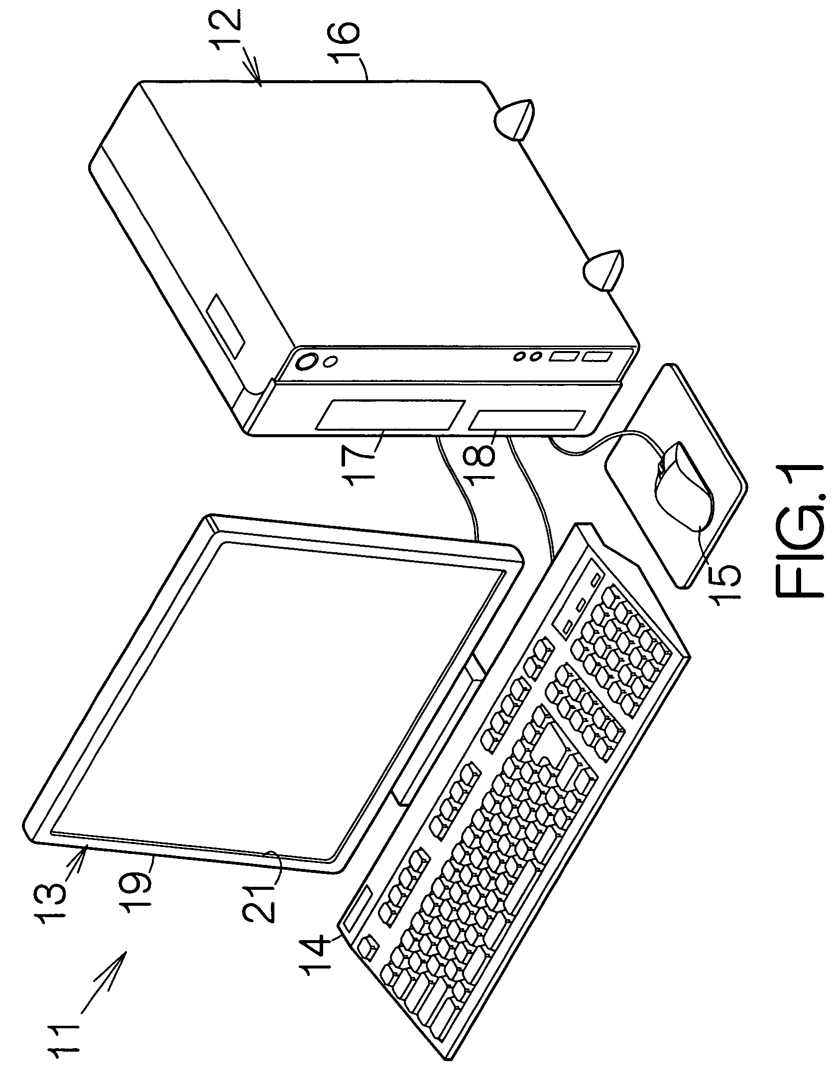
[0023]FIG. 1 is a perspective view schematically illustrating the structure of a desktop computer system 11 as a specific example of an information processing apparatus. The desktop computer system 11 includes a computer 12 as an example of an electronic apparatus and a display apparatus 13 connected to the computer 12. Input devices such as a keyboard 14, a mouse 15 and the like are also connected to the computer 12.

[0024]The computer 12 includes a box-shaped enclosure 16. A so-called motherboard is enclosed in the enclosure 16. As conventionally known, electronic circuit elements such as a CPU (central processing unit), a memory, and the like, are mounted on the motherboard. The central processing unit executes various processing and calculation based on software programs and data temporarily stored in the memory, for example. The software programs and data may be stored in a mass storage such as a hard disk drive (HDD) likewise enclosed within the enclosure 16. The user is allowe...


PUM


Abstract

A cover is coupled to an enclosure body for a relative sliding movement. An opening operating member is attached to the enclosure body. An enclosure includes a sliding mechanism for sliding the cover. When the cover is to be removed, a user operates the opening operating member so as to cause the cover to slide. The user can thus recognize the movable portion of the enclosure. At the same time, the user can recognize the direction of movement of the movable portion, that is, the cover. Even the user who does not remember the operation of releasing can carry out the operation to remove the cover with small force and relatively easily.

Description

CROSS REFERENCE TO RELATED APPLICATIONS[0001]This application is a continuing application, filed under 35 U.S.C. §111(a), of International Application PCT / JP2004 / 011891, filed Aug. 19, 2004, the disclosures of which are hereby incorporated herein by reference.BACKGROUND OF THE INVENTION[0002]1. Field of the Invention[0003]The present invention relates to an electronic apparatus such as a desktop personal computer. In particular, the invention relates to an enclosure defining an inner space.[0004]2. Description of the Prior Art[0005]Generally, a desktop computer includes an enclosure body and a cover coupled to the enclosure body. An electronic component such as a hard disk drive (HDD) is placed within the inner space defined between the enclosure body and the cover. Each of the enclosure body and the cover is an assembly of components. A plurality of boundaries thus appear on the exterior of the computer in addition to the boundary between the enclosure body and the cover.[0006]When...

Claims


Application Information

Patent Timeline
Patent Type & Authority Patents(United States)
IPC IPC(8): H05K5/00
CPCG06F1/181G06F2200/1638
Inventor TAKIZAWA, TOMOHIROIKEDA, KIYOHIKOTSUCHIDA, MAKOTO
Owner FUJITSU CLIENT COMPUTING LTD
Why Eureka
Try Eureka