Reception determination method and system of ray, and radio wave propagation characteristic estimation method using them

a technology applied in the field of ray and determination method and system, can solve the problems of inadequacies, large computational effort, and generally expensive techniques, and achieve the effects of large computational effort, reduced computational complexity, and reduced computational complexity

Inactive Publication Date: 2010-11-30
NEC CORP
View PDF9 Cites 8 Cited by
  • Summary
  • Abstract
  • Description
  • Claims
  • Application Information

AI Technical Summary

Benefits of technology

[0049]In accordance with the first to fifth features of the present invention, the reception point groups to be clearly excluded in the reception determination can be collectively excluded by a unit of the reception point group including them by means of the simple determination calculation. Thereby, since, compared with a conventional technique in which the reception determination having the same calculation load is successively applied to all of the reception points arranged within the observation region, the total number of the reception points for which the reception determination calculation having a large computational efforts is performed can be reduced, entire calculation time can be suppressed.
[0050]The present invention has the sixth feature that it has a configuration wherein, as the region involving the region in the third feature, in which the reception point groups are defined, a sphere circumscribed with the reception point groups is utilized. In accordance with this configuration, since the screening of the reception point groups is conducted by means of the simple determination calculation in which distance determination between a small number of points and straight lines is a main constitution element, the screening processing of the reception point groups can be conducted at a high speed.
[0051]The present invention has the seventh feature that it has a configuration wherein, in case that the reception points are provided in the shape of a planar lattice, and as the region involving the region in which the reception point groups are defined, the sphere circumscribed with the reception point groups is utilized, in the hierarchical grouping processing of the reception points in the first feature, when lattice points which stand in a line on a most outer side form a rectangle, the number of the reception points (most external contour reception points, hereinafter) which stand in a line on two sides thereof is resolved into a sum of an (a is an integer equal to or more than 1, and n is an integer including 0), and after square regions in which each factor of the generated an by means of the resolution is assumed to be the number of the most external contour reception points are newly generated, out of these square regions, the regions having a greater area are spread inside said observation point region as much as possible, and further, by successively dividing each of the spread square regions into a2 square regions having the same area, a hierarchical group of the reception points is structured. In accordance with this configuration, an arbitrary number of the reception points provided in the shape of a planar lattice can be easily divided into hierarchical groups.
[0052]The present invention has the eighth feature that it has a configuration wherein the screening determination of the reception point groups in the second feature is conducted by means of the intersection determination of a region sandwiched between two infinite planes including each barrier, respectively, which is positioned at both ends of the ray that would be a subject of the reception determination, and the region defining the reception point groups. In accordance with this configuration, in case that the region defining the reception point groups is a polyhedron or a polygon, the number of apexes of which is less, and an interval of said barrier is narrow, compared with a case where the intersection determination of the region involving the region in which the reception point groups are defined and the region defined in the vicinity of the ray is used together, a similar degree of a screening effect of the reception point groups can be realized by means of simpler determination calculation.
[0053]The present invention has the ninth feature that it has a configuration wherein, in the screening determination of the reception point groups in the second feature, when it is determined whether or not the reception point groups are divided into a smaller scale of reception point groups, it is conducted by considering a value of a cost function defined in advance. In accordance with this configuration, by appropriately defining the cost function according to the situation, the division of the reception point groups is finished at a desired arbitrary hierarchy, and it is possible to move to the reception determination of the internal reception points, and flexible and efficient reception determination processing can be realized.
[0054]The present invention has the tenth feature that it has a configuration wherein, as the region involving the reception point groups in the third feature, like FIG. 29, a region defined by a combination of regions divided by singular or plural planes is used. In accordance with this configuration, since it is possible to reduce null regions where the reception points do not exist, which might occurs in case that, like FIG. 16, as the region involving the region in which the reception point groups are defined, the circumscribed sphere is used, unnecessary reception determination calculation of the reception points within the reception point groups and the ray can be reduced.

Problems solved by technology

However, a method in which the base unit and codeless handset are installed in real environment to study the arrangement of the base unit by means of actual measurement generally requires tremendous costs.
Although this technique was conventionally used for application of a base station arrangement design or the like of outdoor mobile communication, it is generally an expensive technique since a number of actually measured data are required for determining the propagation loss estimation formula of the said environment with high accuracy.
In addition, since this technique is one for statistically obtaining an average tendency of the radio wave propagation characteristic in a somewhat wide range, it is not appropriate for environment wherein the propagation characteristic tends to vary widely due to diversification of an indoor arrangement of an appliance, a wall or the like, and application for obtaining the local propagation characteristic in a comparatively narrow range even out of doors.
However, as described in a Non-Patent Publication 1, out of the deterministic techniques, in many techniques like an FDTD, a finite element method and so forth, a computational effort necessary for the analysis becomes huge as a wavelength becomes short compared with an analysis subject region of the propagation characteristic.
Out of the ray tracing methods, compared with the launching method, a calculation load in the imaging method is much larger.
However, even in case that these techniques for speeding-up are applied, generally an estimation speed of the imaging method is slower than that of the launching method.
On the other hand, generally, there are many obstacles inside the analysis space.
Accordingly, in a case where a highly accurate estimation is conducted under real environment, a calculation load of the path tracking generally becomes large.
On the other hand, if the total number of the reception points is reduced to suppress the calculation time required for the reception determination, there is a task that it becomes difficult to look through the propagation characteristic of the entire observation region with a higher accuracy.
A reason thereof is that, in case that the reception points are arranged inside the observation region in a lattice shape for the purpose of looking through the propagation characteristic of the entire observation region, when the number of the entire reception points is reduced, an individual lattice interval is broadened, and it becomes difficult to understand a tendency of the local propagation characteristic.

Method used


Image

  • Reception determination method and system of ray, and radio wave propagation characteristic estimation method using them
  • Reception determination method and system of ray, and radio wave propagation characteristic estimation method using them
  • Reception determination method and system of ray, and radio wave propagation characteristic estimation method using them

Examples


third embodiment

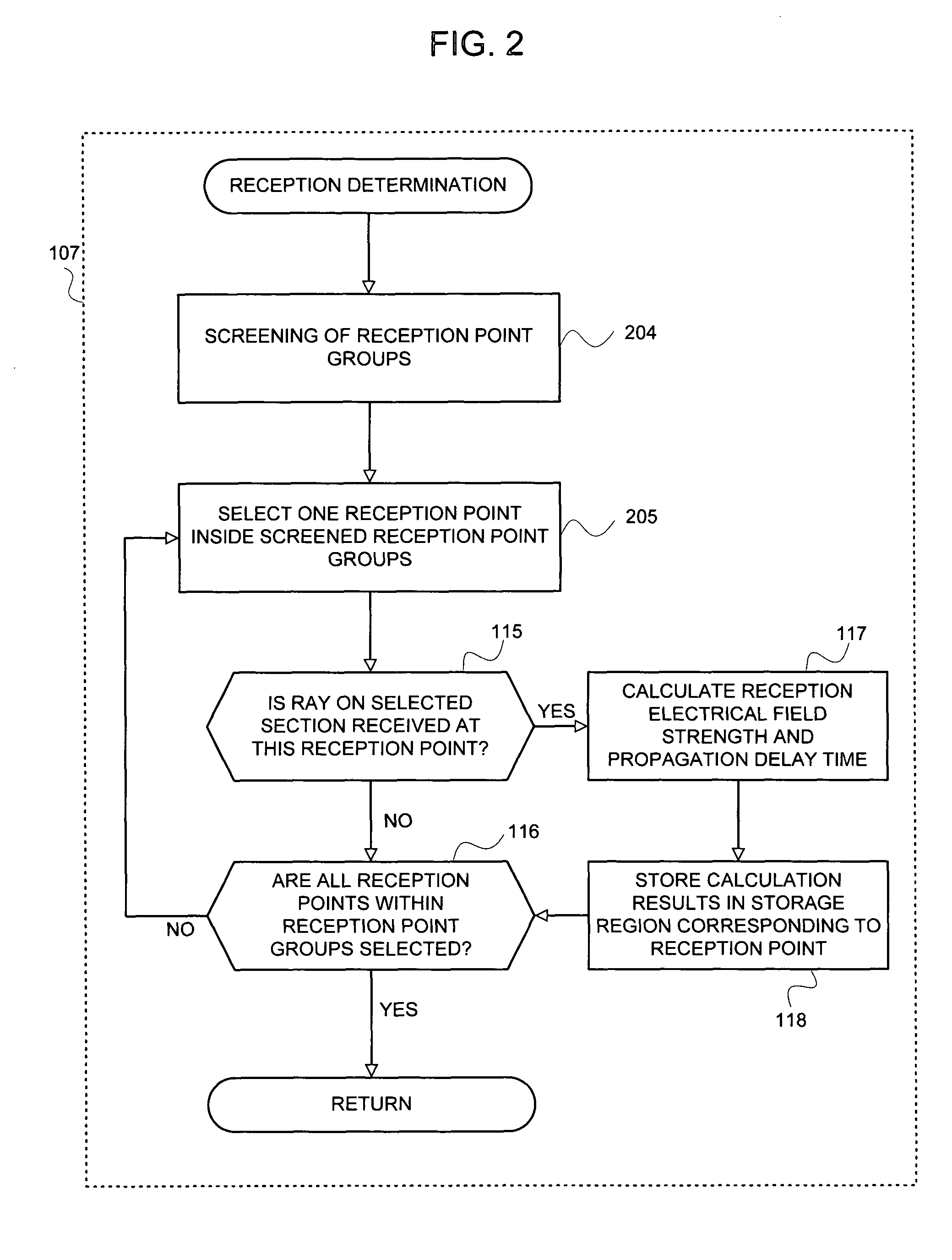
[0135]In the third embodiment, after performing the parameter initialization of FIG. 3, first, one non-selected reception point group ri is selected from the sets Ai at a step 706. Next, it is determined whether or not this reception point group ri meets the exclusion condition of the reception determination, which is defined in advance (step 707). Here, if it is determined that the exclusion condition is met, the selected reception point group ri is discarded, and in order to select a new reception point group ri, at a step 710, it is determined whether or not non-selected reception point groups exist in the sets Ai. If it is determined in this determination that the non-selected reception point groups exist, the process returns to the step 706, and the new reception point group ri is selected.

[0136]On the other hand, if it is determined on the determination at the step 707 that the reception point group ri does not meet the exclusion condition of the reception determination, the p...

first embodiment

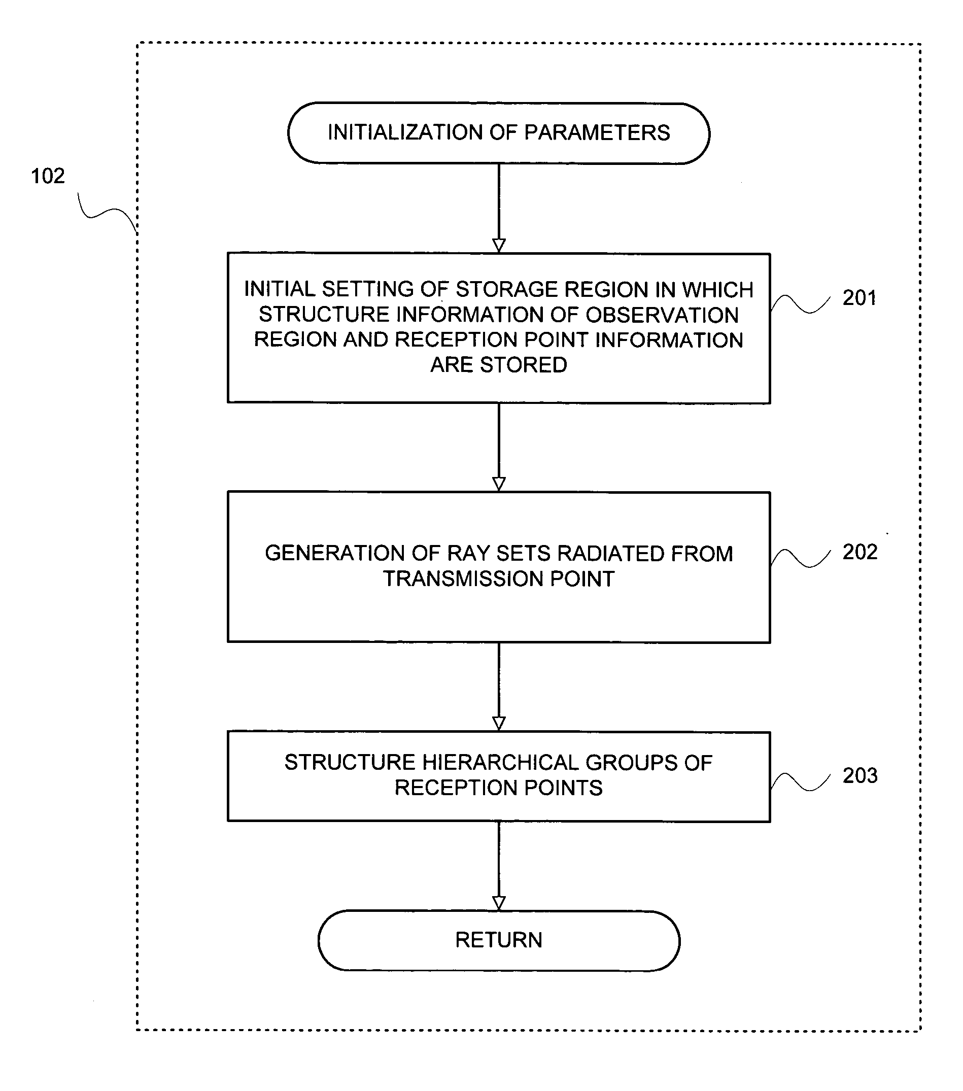
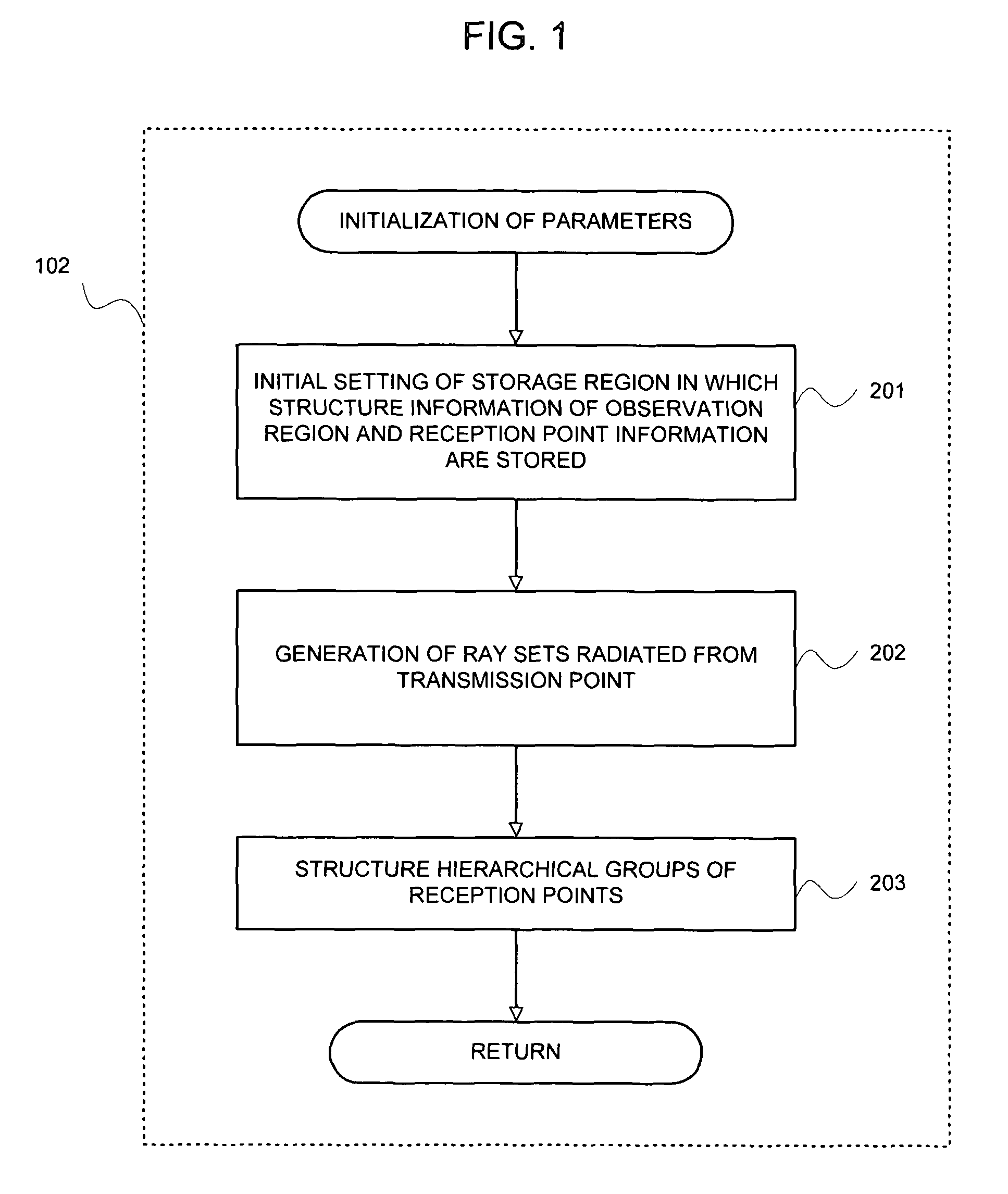
[0142]In this manner, the hierarchical grouping of the reception points inside the observation region can be conducted by means of the partial regions having an arbitrary shape, and the hierarchical grouping can be conducted by using a combination of the partial regions having different shapes, such as a combination of a quadrangle and a triangle. Also, the maximum number of the hierarchies in conducting the division and hierarchization can be set inhomogeneously for every place of the observation region. Further, although, in the first embodiment, a case where the reception points stand in line in the shape of lattice on the two-dimensional plane was raised, the reception determination processing of the present invention, in which the hierarchical grouping of the reception points is conducted, is effective even in a case where the reception points stand in line on the two-dimensional plane inhomogeneously. Further, the reception determination processing in accordance with the prese...


PUM


Abstract

Reception points arranged inside an observation region are divided into groups for a plurality of reception points, and a hierarchical structure in which a reception point group having a large scale involves a smaller scale of plural reception point groups is structured in advance. In accordance with determination criteria defined in advance, the reception point groups involving the reception points which need reception determination processing with a ray are successively screened from the reception point groups having a large scale to a smaller scale of reception point groups, and the final reception determination of a ray and the reception points is applied only to the reception points involved in the screened reception point groups. Thereby, since a reception point group which is clearly excluded in the reception determination by means of a conventional technique can be collectively excluded by a reception point group unit involving them, the total number of the reception points to which the reception determination is applied can be reduced. As a result, required time for propagation estimation can be suppressed more than a conventional method.

Description

BACKGROUND OF THE INVENTION[0001]The present invention relates to a reception determination method and system of a ray, and a radio wave propagation characteristic estimation method using them, and especially, to a reception determination method and system of a ray in radio wave propagation characteristic estimation by means of a geometric optical technique, and a radio wave propagation characteristic estimation method using them.[0002]In order to efficiently arrange a base unit (base station) in a radio communication system, it becomes important that a radio wave propagation characteristic such as a propagation loss and delay spread can be predicted on a computer with good accuracy and at high speed. Usually, an arrangement of the base unit in the radio communication system is conducted by try and error so that a region where communication is desired would be a range where a codeless handset (terminal) can communicate. However, a method in which the base unit and codeless handset a...

Claims


Application Information

Patent Timeline
Patent Type & Authority Patents(United States)
IPC IPC(8): H04W24/00H04B7/26H04B17/00H04B17/391H04W16/18H04W24/06
CPCH04W16/18
Inventor WATANABE, YOSHINORI
Owner NEC CORP
Why Eureka
Try Eureka