Submersible vehicle object ejection system using a flywheel driven boost pump

a technology of ejection system and vehicle, which is applied in the direction of underwater equipment, special-purpose vessels, vessel construction, etc., can solve the problems of relatively high maintenance frequency, relatively high cost of components, and add to the overall vehicle weigh

Inactive Publication Date: 2010-12-07
HONEYWELL INT INC
View PDF27 Cites 5 Cited by
  • Summary
  • Abstract
  • Description
  • Claims
  • Application Information

AI Technical Summary

Problems solved by technology

These components take up space within a submersible vehicle hull, and add to the overall vehicle weight.
Moreover, because operation with a relatively quiet acoustic signature may be desirable, these components can be relatively costly to design, produce, and install, and can exhibit relatively high maintenance frequencies.
However, the size of the electric motor that is needed to meet system functional requirements can be relatively large and costly.

Method used


Image

  • Submersible vehicle object ejection system using a flywheel driven boost pump
  • Submersible vehicle object ejection system using a flywheel driven boost pump
  • Submersible vehicle object ejection system using a flywheel driven boost pump

Examples


Embodiment Construction

[0012]The following detailed description of the invention is merely exemplary in nature and is not intended to limit the invention or the application and uses of the invention. Furthermore, there is no intention to be bound by any theory presented in the preceding background of the invention or the following detailed description of the invention.

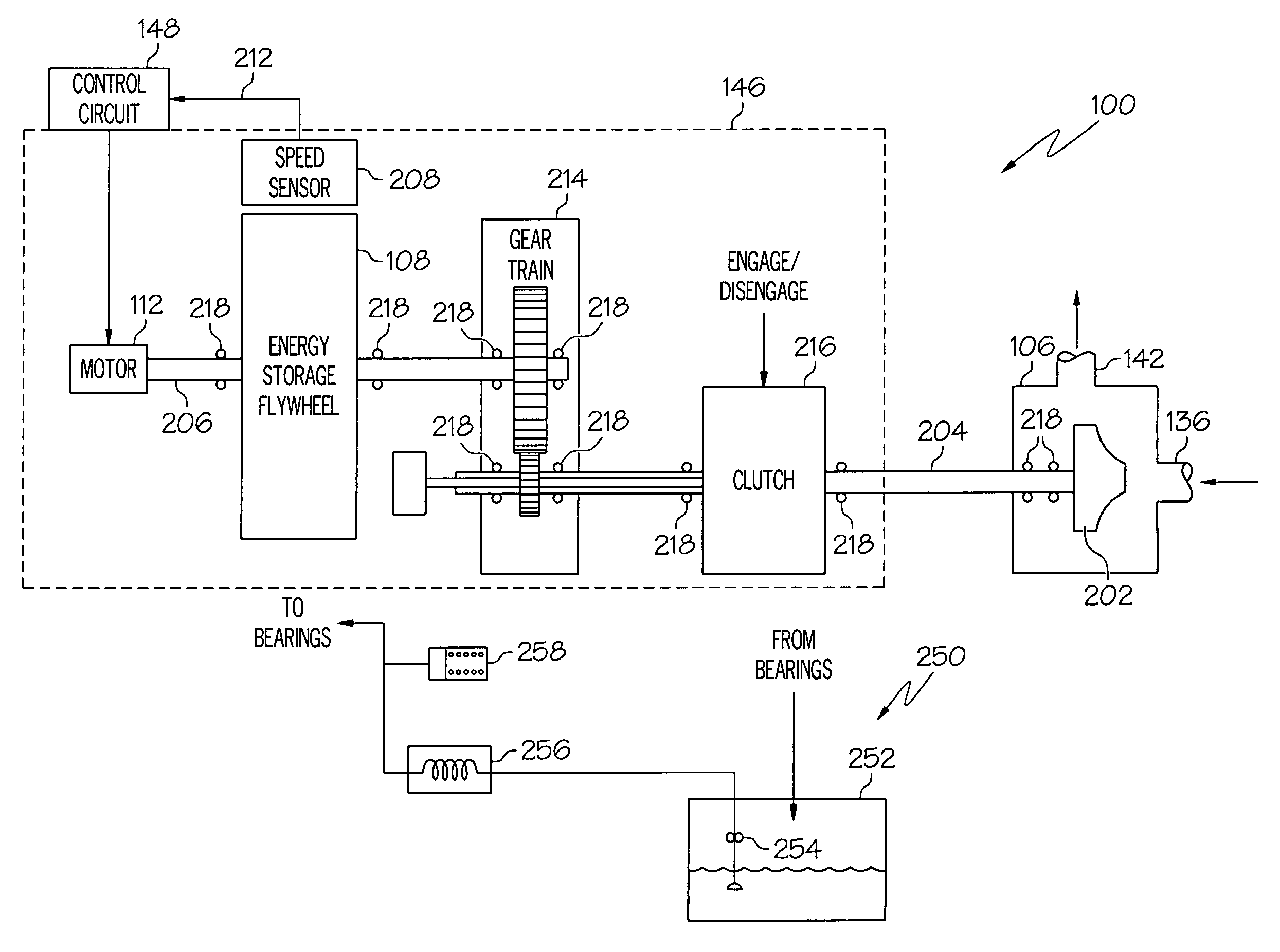
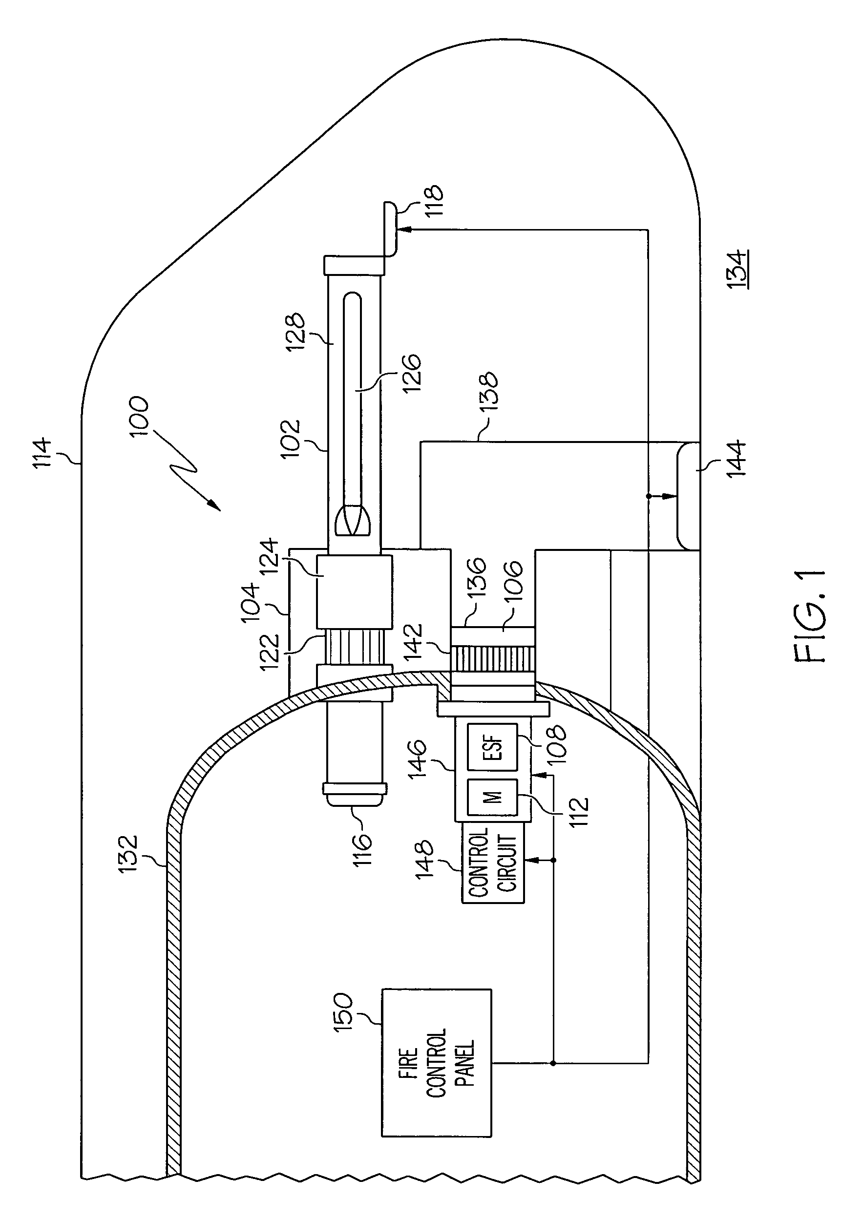
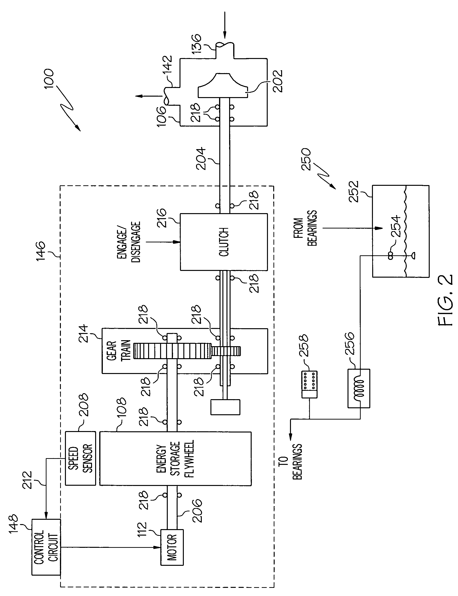
[0013]Referring now to FIG. 1, a submersible vehicle object ejection system 100 is illustrated schematically and includes one or more ejection tubes 102 (for clarity, only one shown), an impulse tank 104, a fluid pump 106, an energy storage flywheel 108, and a motor 112, all disposed within, or at least partially within, the vehicle hull 114. The ejection tubes 102 each include a breach door 116, a muzzle door 118, a plurality of fluid inlets 122, and a slide valve 124. The breach doors 116 are opened to load a weapon 126, or other object, into an inner volume 128 of the ejection tubes 102, and are then closed to seal the inner volume 128 fr...


PUM


Abstract

An object ejection system uses an energy storage flywheel to drive the fluid pump that is used to pressurize the ejection tubes. The energy storage flywheel is periodically spun-up using an electric motor. The energy stored in the energy storage flywheel is used, when needed, to drive the fluid pump and supply pressurized fluid to an impulse tank. The pressurized fluid in the impulse tank is used to eject an object, such as a weapon, from one or more ejection tubes.

Description

TECHNICAL FIELD[0001]The present invention relates to a submersible vehicle object ejection system and, more particularly, to a object ejection system that uses a flywheel driven boost pump to pressurize the object system ejection tubes.BACKGROUND[0002]Many submersible vehicles, such as military submarines, include one or more object ejection systems. An object ejection system may be used to eject various types of objects from the vehicle. Such objects may include, for example, sonar buoys, counter measure devices, and various types of weapons, such as torpedoes and / or missiles. A typical object ejection system that is used to eject weapons from a submersible vehicle includes one or more weapon ejection tubes, an impulse tank, a boost pump, and an air turbine.[0003]A weapon may be launched from an ejection tube by fluidly communicating the ejection tube with an impulse tank by, for example, opening a slide valve on the ejection tube, and then pressurizing the impulse tank with fluid...

Claims


Application Information

Patent Timeline
Patent Type & Authority Patents(United States)
IPC IPC(8): B63G8/32
CPCB63G8/30B63G8/32B63G8/38F41F3/10
Inventor RAYNER, JEFFREY S.WINGETT, PAUL T.TOON, JOHN R.BRAULT, SHARON K.
Owner HONEYWELL INT INC
Why Eureka
Try Eureka