
Wireless electrical apparatus controller device and method of use

Active Publication Date: 2010-12-07
WIRELSS TELMATICS
View PDF23 Cites 78 Cited by
  • Summary
  • Abstract
  • Description
  • Claims
  • Application Information

AI Technical Summary

Benefits of technology

[0017]Aspects of the present invention teach certain benefits in construc

Problems solved by technology

The prior art described above teaches an apparatus for addressably controlling remote units, a sign board lighting control system, a radio paging electrical load control system and device, programmable remote control systems for electrical apparatuses, a remote control method for a process, an intelligent outdoor lighting control system, an LED traffic light intensity controller, an urban remote surveillance system for street lamps, an architecture of ballast with integrated RF interface, and universal lighting network methods and systems, but does not teach a wireless electrical apparatus control system that, when the wireless network, the host server or the apparatus' own power are down for a period of time, is yet capable of functioning properly and efficiently and without the need for time data to be sent separately.

Method used


Image

  • Wireless electrical apparatus controller device and method of use
  • Wireless electrical apparatus controller device and method of use
  • Wireless electrical apparatus controller device and method of use

Examples


Embodiment Construction

[0026]The above described drawing figures illustrate aspects of the invention in at least one of its exemplary embodiments, which are further defined in detail in the following description.

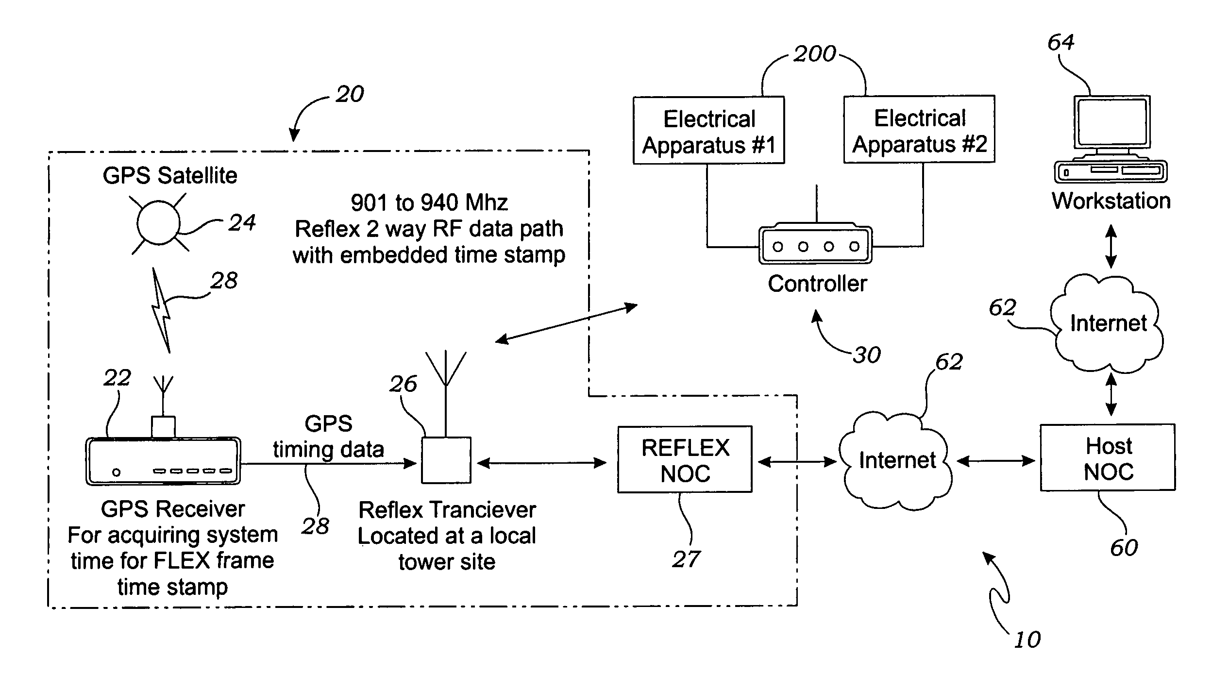
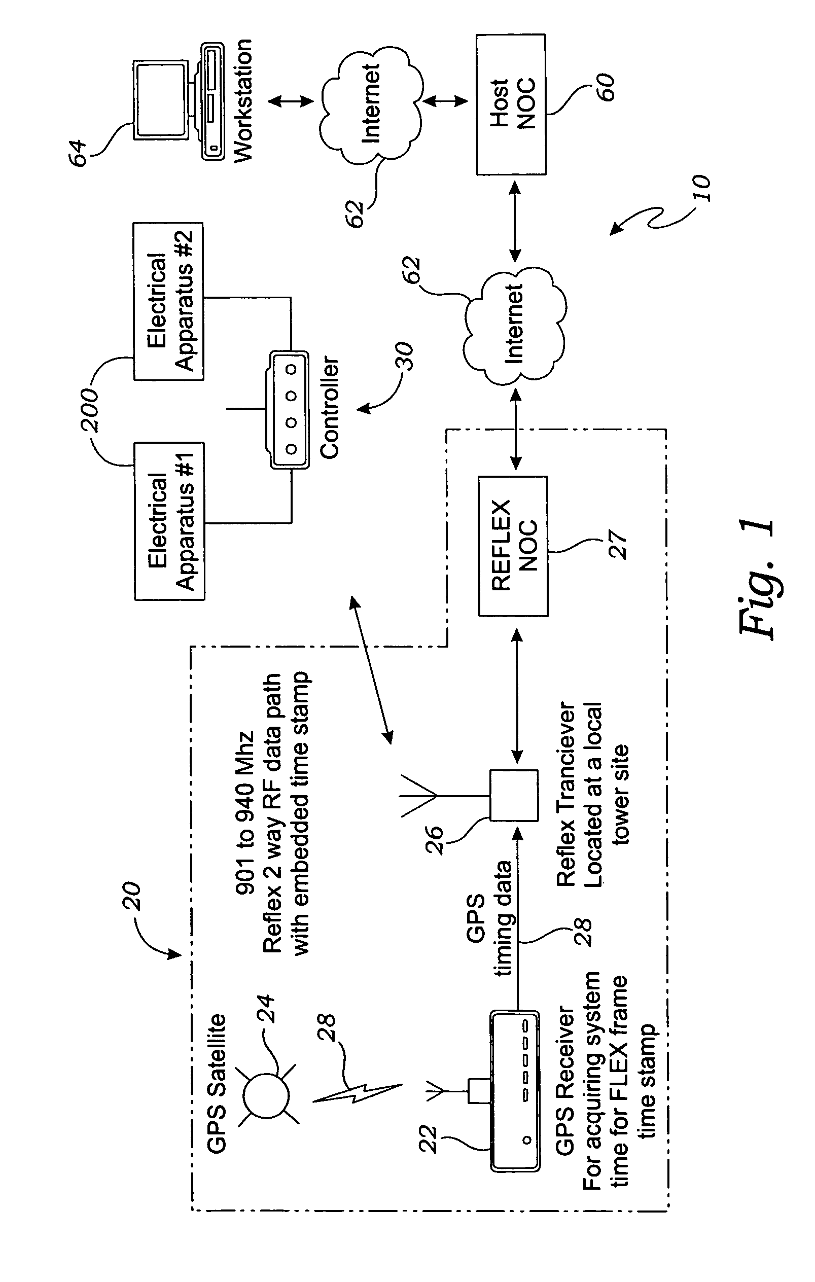
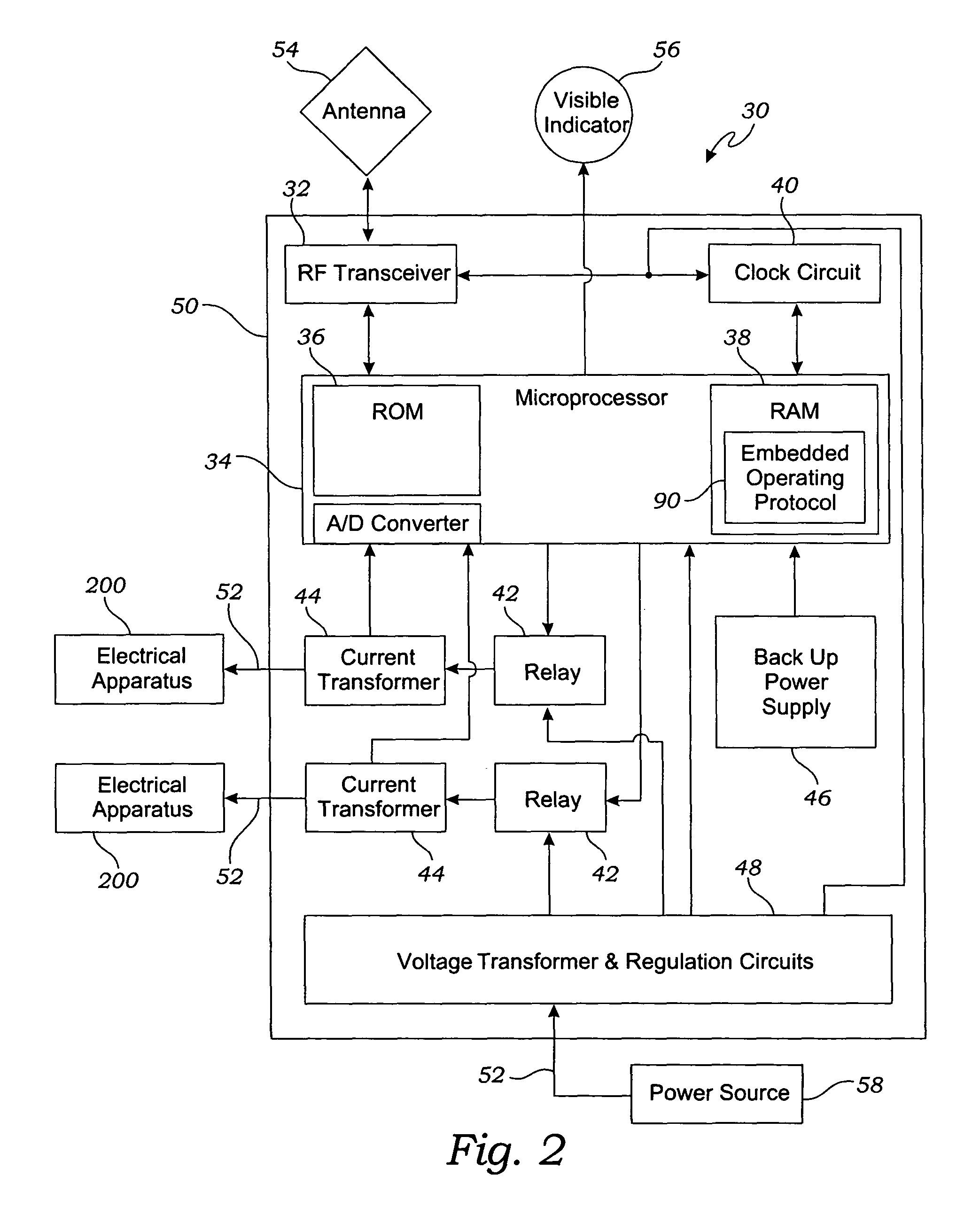
[0027]The present invention is generally directed to a system 10 for controlling one or more electrical apparatuses 200 comprising a wireless network 20 and one or more processor / transceiver control units 30 connected to the electrical apparatuses 200 and communicating with a host network operations center 60 over the wireless network 20. In the exemplary embodiment, the wireless network 20 is a two-way ReFLEX network as is known and used in the art. As such, the wireless network 20 includes a first transceiver 22 configured to acquire and relay real-time data 28 from a global positioning system satellite 24 and a second transceiver 26 configured to receive the real-time data 28 from the first transceiver 22 and to continuously transmit the real-time data 28 to the control unit 30. The processor / t...


PUM


Abstract

A device for controlling one or more electrical apparatuses comprising a processor / transceiver control unit connected to each electrical apparatus and having at least one microprocessor wired to a transceiver and a clock circuit that keeps real-time onboard, the microprocessor storing an operating protocol according to which the control unit controls power to the electrical apparatus at real-time as kept by the clock circuit. The control unit's microprocessor may be further configured to read and store a nominal voltage for the electrical apparatuses and to compare the nominal voltage to the electrical apparatuses' operating voltage so as to monitor and report on their operation.

Description

INCORPORATION BY REFERENCE[0001]Applicants hereby incorporate herein by reference any and all U.S. patents and U.S. patent applications cited or referred to in this application.BACKGROUND OF THE INVENTION[0002]1. Field of the Invention[0003]Aspects of this invention relate generally to electrical apparatus controllers, and more particularly to wireless electrical apparatus control devices.[0004]2. Description of Related Art[0005]The following art defines the present state of this field:[0006]U.S. Pat. No. 4,454,509 to Buennagel et al. is directed to a load management system which includes a central message generator and a plurality of addressable remote load controllers which selectively connect and disconnect high power deferrable loads to and from a power source in response to transmitted messages. The load controllers include means for translating coded tone pair inputs into digital data. Tones selected from three such tone pairs are used in one scheme, where a tone selected from...

Claims


Application Information

Patent Timeline
IPC IPC(8): G08C19/00
CPCG08C17/02G08C2201/42G08C2201/91
Inventor ROSS, ALLAN L.MCWHIRTER, WILLIAM D.WEAVER, JOHN S.JORDAN, PAUL R.
Owner WIRELSS TELMATICS
Learn More