Exhaust emission purifying apparatus for engine

a technology for purifying apparatus and exhaust gas, which is applied in mechanical equipment, machines/engines, separation processes, etc., can solve the problems of offensive odor and offensive odor, and achieve the effects of reducing the concentration of residual gas, and preventing the reeking of gas odor

Active Publication Date: 2010-12-14
VOLVO LASTVAGNAR AB
View PDF87 Cites 45 Cited by
  • Summary
  • Abstract
  • Description
  • Claims
  • Application Information

AI Technical Summary

Benefits of technology

[0008]Therefore, in view of the above conventional problems, the present invention has an object to provide an exhaust emission purifying apparatus for an engine, for returning the gas in an upper space of a storage tank to an intake system or an exhaust system, or appropriately discharging the gas while oxidizing the gas by an oxidation catalyst, or preventing cooling water from being circulated within the storage tank when the cooling water heated by the engine has a temperature higher than a predetermined temperature, so as to suppress the offensive odor which generates when the storage tank is closably opened.
[0010]In accordance with the exhaust emission purifying apparatus according to claim 2, the first operation control device operates the first discharge-forcing device for a predetermined period of time, in order to avoid the excessive energy consumption.
[0017]In accordance with the exhaust emission purifying apparatus according to claim 9, the second operation control device operates the second discharge-forcing device for a predetermined period of time, in order to avoid the excessive energy consumption.
[0028]Consequently, even in a situation where the gas generates from the reducing agent in the storage tank, since the gas in the upper space of the storage tank is forcibly discharged, the concentration of the residual gas is significantly lowered. Therefore, if a protective cap is detached in order to fill the reducing agent into the storage tank through uncapped injection port, an operator can be almost unconscious of the odor of the reducing agent, and further, the offensive odor discharged during the opening and closing operation of the storage tank can be appreciably reduced.
[0030]Consequently, even in the situation where the gas generates from the reducing agent in the storage tank, since the gas in the upper space of the storage tank is forcibly discharged, the concentration of the residual gas is significantly lowered. Therefore, if the injection cap is detached in order to replenish the reducing agent into the storage tank, the operator will be able to be unconscious of the odor of the reducing agent, and further, the offensive odor discharged during the opening and closing operation of the storage tank can be reduced. Further, since the gas forcibly discharged from the upper space of the storage tank is temporarily adsorbed by the adsorbing device and thereafter is gradually desorbed, and is oxidized in the oxidation catalyst converter, it is possible to prevent the gas odor from reeking around the storage tank.
[0031]Moreover, according to the further exhaust emission purifying apparatus of the present invention, nitrogen oxides in the exhaust emission of the engine is reductively purified in the reduction catalyst using the reducing agent which is supplied from the storage tank by the reducing agent supply device. Further, since the heating medium heated by the engine is circulated within the storage tank storing the reducing agent, the reducing agent in the storage tank is heated to enable the prevention of the freeze of the reducing agent. At this time, when the temperature of the heating medium being circulated within the storage tank is higher than the third predetermined temperature, since the passage leading the heating medium into the storage tank is blocked, it is possible to prevent the heating medium whose temperature is higher than the third predetermined temperature from being circulated within the storage tank. Then, the third predetermined temperature is set to be slightly lower than the lower limit temperature at which the gas generates from the reducing agent, so that the generation of gas from the reducing agent in the storage tank can be suppressed. Therefore, if the operator opens an injection port of the storage tank, it is possible to suppress the discharge of the gas from the injection port, to thereby suppress generation of the offensive odor.

Problems solved by technology

Then, for example when the storage tank is to be replenished with the urea aqueous solution, if an operator detaches a protective cap of the storage tank, there might occur such a situation that that the filled ammonical gas comes to leak toward the outside, to thereby produce the offensive odor.
Such offensive odor will be produced not only when the aqueous urea solution is used as the reducing agent but also when a diesel oil which mainly contains the aqueous ammonia solution, hydrocarbon or the like, is used.

Method used


Image

  • Exhaust emission purifying apparatus for engine
  • Exhaust emission purifying apparatus for engine
  • Exhaust emission purifying apparatus for engine

Examples


first embodiment

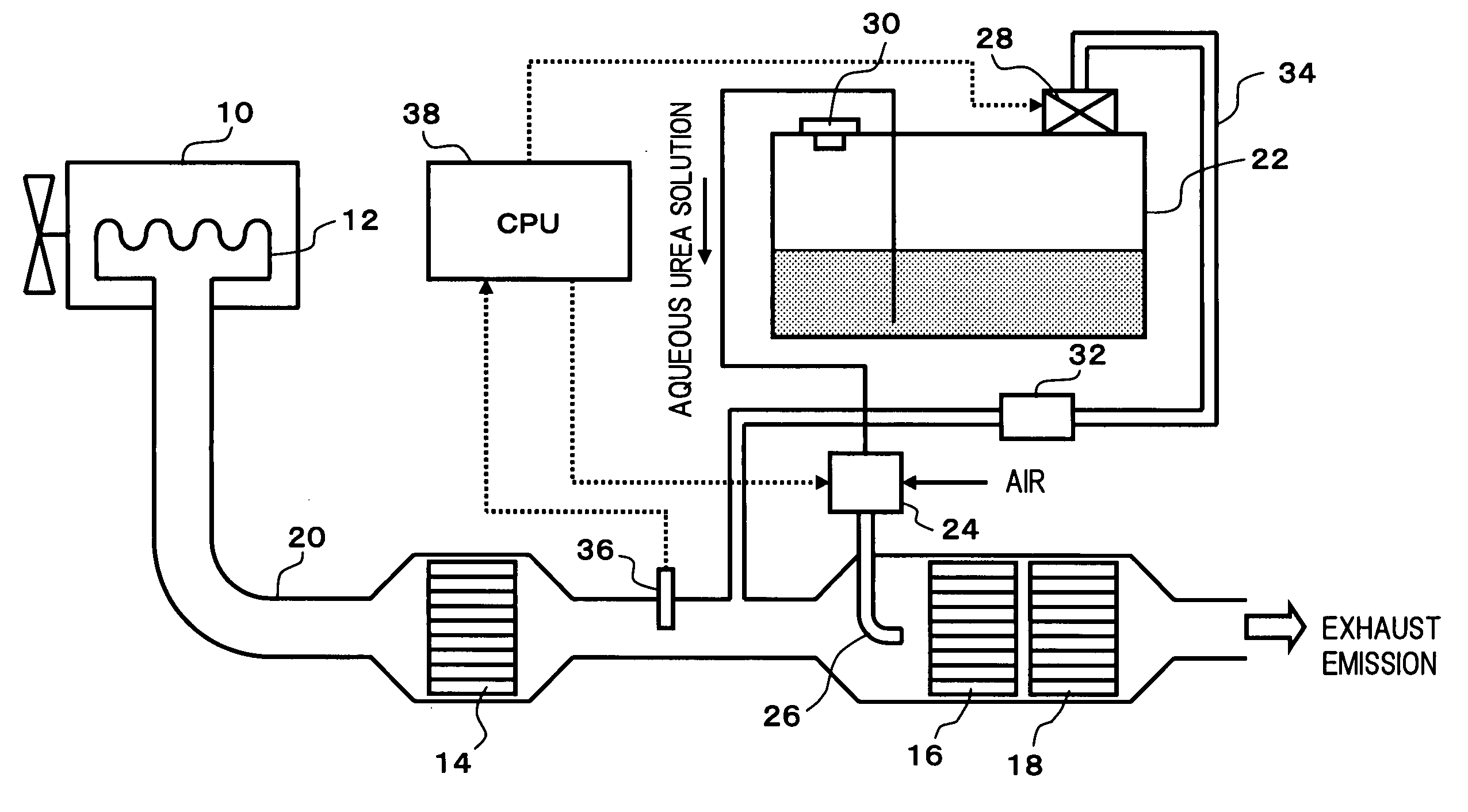
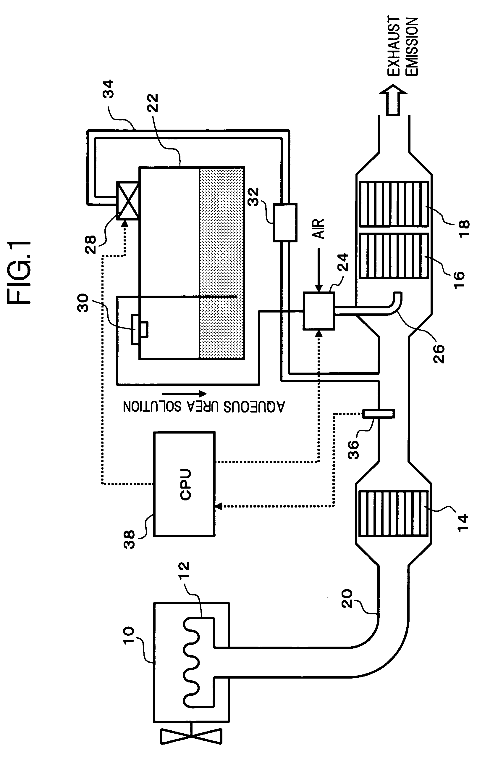
[0039]FIG. 1 shows a configuration of an exhaust emission purifying apparatus according to the present invention. The exhaust emission of an engine 10, which is discharged from an exhaust manifold 12 toward the downstream of the exhaust manifold 12, passes through an exhaust pipe 20 to which an oxidation catalyst 14, a NOx reduction catalyst 16 and an ammonia slip oxidation catalyst 18 (reducing agent oxidation catalyst) are respectively disposed, to be discharged into the atmosphere. Further, a liquid reducing agent stored in a storage tank 22 which passed through a reducing agent supply device 24 and an injection nozzle 26, is injected together with the air to be supplied to the exhaust upstream of the NOx reduction catalyst 16.

[0040]Here, in the present embodiment, as the liquid reducing agent, the aqueous urea solution which easily generates ammonia by the hydrolysis is used. However, as the liquid reducing agent, diesel oil mainly containing hydrocarbon or the like may be used ...

second embodiment

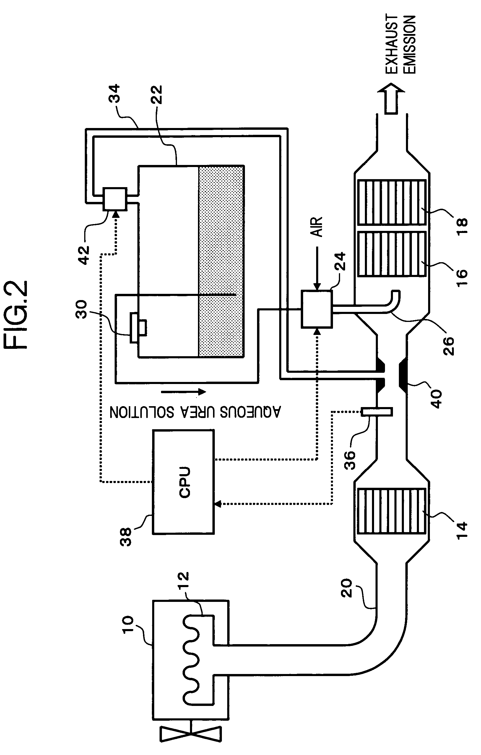
[0048]In place of the electric fan 28 in the above embodiment, as shown in a second embodiment shown in FIG. 2, a venturi 40 may be disposed to the exhaust pipe 20 on the upstream side of the NOx reduction catalyst 16, to discharge the ammonia series gas in the upper space of the storage tank 22 to this venturi 40. In this case, the configuration may be such that a normally closed electromagnetic switching valve 42 is disposed to the piping 34, to open the electromagnetic switching valve 42 at the timing for operating the electric fan 28. Thus, the ammonia series gas in the upper space of the storage tank 22 is forcibly discharged by the exhaust emission which passed through the venturi 40 to reduce the pressure thereof. Therefore, the energy for driving the electric fan 28 is no longer necessary, and the battery consumption or the like can be suppressed. In this embodiment, the first discharge-forcing device comprises the piping 34 and the venturi 40.

[0049]In each of the above embo...

fourth embodiment

[0082]Next, there will be described an operation of the exhaust emission purifying apparatus in the above configuration. The exhaust emission from the engine 10 passes through the exhaust pipe 20 to be led into the NOx reduction catalyst 16. At this time, the controller 82 receives the engine operating conditions, such as the rotation speed, the load and the like, of the engine 10, from the operating condition detecting sensor 80, and controls operating of the pump in the reducing agent supply device 24 and the electromagnetic switching valve 62, so that the urea water of the optimum amount corresponding to the engine operating conditions is injected from the injection nozzle 26 to be supplied into the exhaust pipe 20. As a result, NOx in the exhaust emission is reductively removed with efficiency by the NOx reduction catalyst 16.

[0083]When the temperature of the urea water in the storage tank 22 is equal to or lower than the predetermined temperature Ta, namely, there is a possibil...


PUM

PropertyMeasurementUnit
activating temperatureaaaaaaaaaa
temperatureaaaaaaaaaa
activating temperatureaaaaaaaaaa

Abstract

A NOx reduction catalyst and an ammonia slip oxidation catalyst are disposed in an exhaust system in this order, and also, an electric fan is disposed on piping which communicates an upper space of a storage tank storing therein a reducing agent with the exhaust upstream of the NOx reduction catalyst. Then, when the temperature of the ammonia slip oxidation catalyst reaches or exceeds the temperature for activating a catalyst thereof, the electric fan is operated for a predetermined period of time, so that the gas (ammonia series gas) in the upper space of the storage tank is forcibly discharged to the upstream side of the NOx reduction catalyst. Further, a discharge-forcing device, such as an electric fan or the like, forcibly discharging the gas in the upper space of the storage tank, an adsorbing device temporarily adsorbing thereto the forcibly discharged gas and an oxidation catalyst oxidizing the gas desorbed from the adsorbing device, may be disposed to the storage tank in this order.

Description

CROSS-REFERENCES TO RELATED APPLICATIONS[0001]This application is the National Stage of International Application No. PCT / JP2004 / 012743, filed on Sep. 2, 2004.BACKGROUND OF THE INVENTION[0002]1. Field of the Invention[0003]The present invention relates to an exhaust emission purifying apparatus for an engine (to be referred to as exhaust emission purifying apparatus hereunder), for reductively removing, using a reducing agent, nitrogen oxides (NOx) in the exhaust gas or emission (it will be referred to as “exhaust emission” hereinafter throughout the description and claims), which is exhausted from the engine, and in particular, to a technology for reducing an offensive odor which is produced when a storage tank storing the reducing agent is opened or closed.[0004]2. Description of the Related Art[0005]Japanese Unexamined Patent Publication No. 2000-27627 disposes an exhaust emission purifying apparatus which proposes a catalyst purifying system to remove NOx contained in the engine...

Claims


Application Information

Patent Timeline
Patent Type & Authority Patents(United States)
IPC IPC(8): F01N3/00F01N3/20F01N11/00F01N13/02
CPCB01D53/9409F01N3/105F01N3/106F01N3/206F01N3/208F01N11/002F01N13/0097F01N13/009B01D2251/2062F01N2610/02F01N2610/08F01N2610/10F01N2610/1406F01N2610/1486Y02T10/47Y02T10/24Y02T10/12Y02T10/40
Inventor MASUDA, KOUJIHIRATA, KIMINOBUAKAGAWA, HISASHINAKAMURA, SHUICHIUENO, HIROKISAKAI, IKUO
Owner VOLVO LASTVAGNAR AB
Why Eureka
Try Eureka