Exhaust emission purifying apparatus for engine
- Summary
- Abstract
- Description
- Claims
- Application Information
AI Technical Summary
Benefits of technology
Problems solved by technology
Method used
Image
Examples
first embodiment
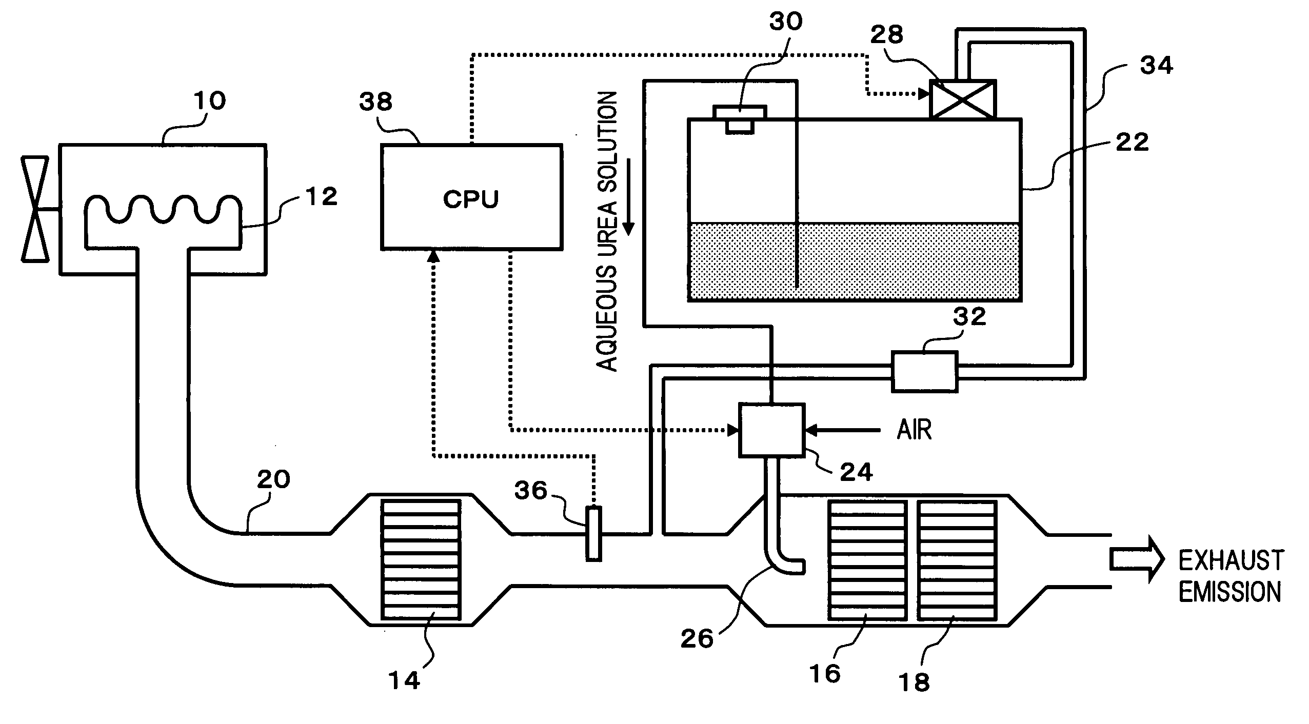
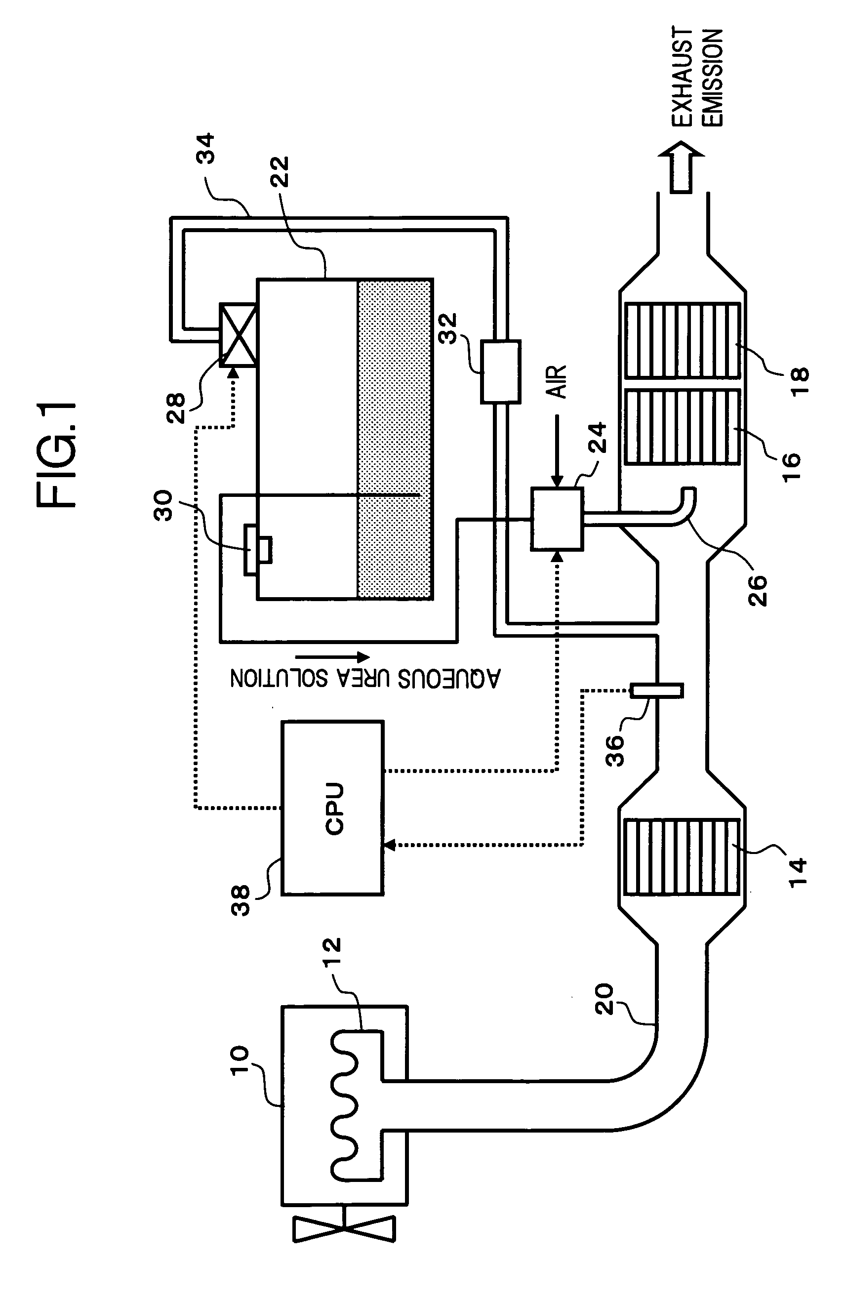
[0039]FIG. 1 shows a configuration of an exhaust emission purifying apparatus according to the present invention. The exhaust emission of an engine 10, which is discharged from an exhaust manifold 12 toward the downstream of the exhaust manifold 12, passes through an exhaust pipe 20 to which an oxidation catalyst 14, a NOx reduction catalyst 16 and an ammonia slip oxidation catalyst 18 (reducing agent oxidation catalyst) are respectively disposed, to be discharged into the atmosphere. Further, a liquid reducing agent stored in a storage tank 22 which passed through a reducing agent supply device 24 and an injection nozzle 26, is injected together with the air to be supplied to the exhaust upstream of the NOx reduction catalyst 16.
[0040] Here, in the present embodiment, as the liquid reducing agent, the aqueous urea solution which easily generates ammonia by the hydrolysis is used. However, as the liquid reducing agent, diesel oil mainly containing hydrocarbon or the like may be used...
second embodiment
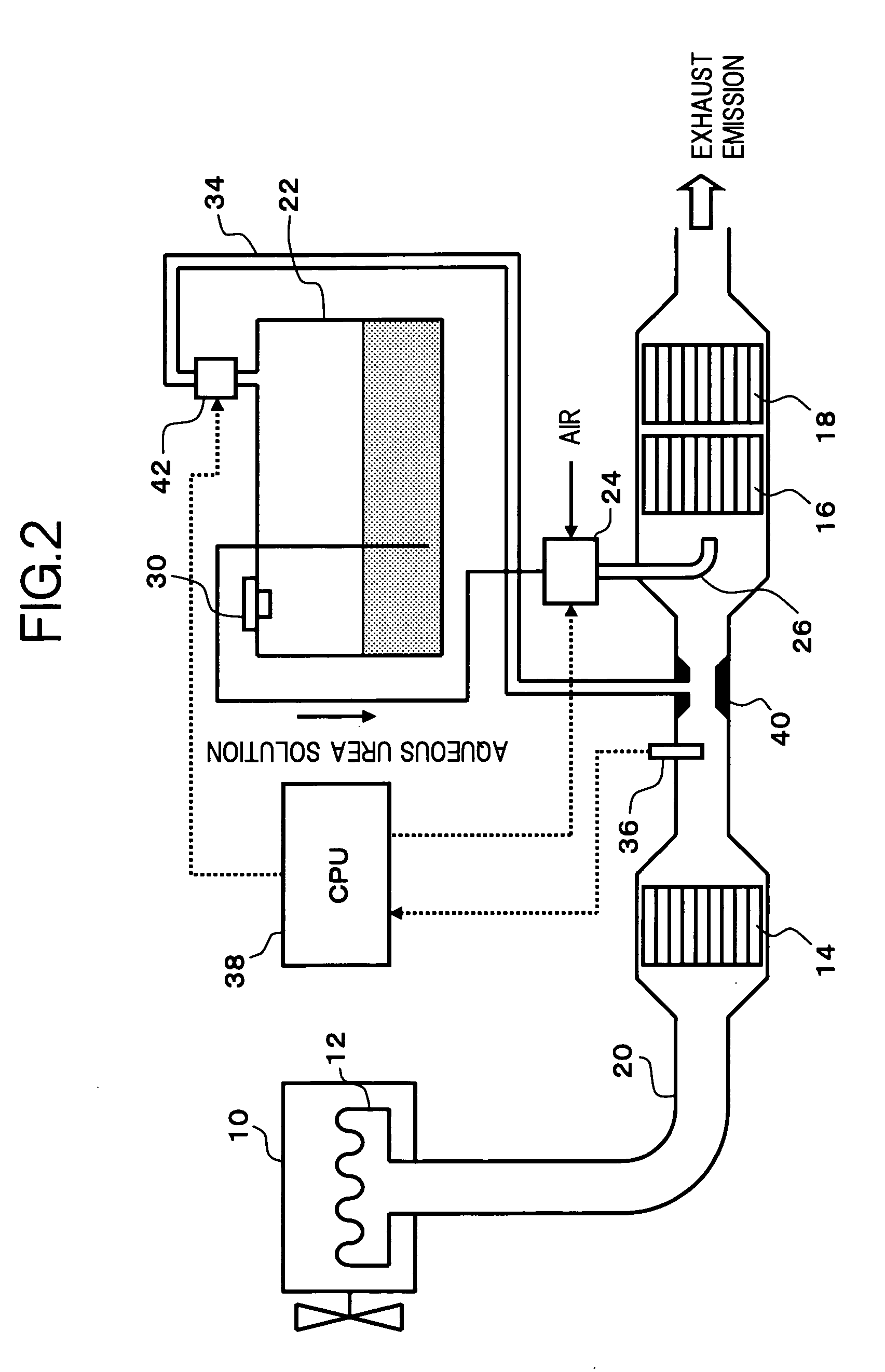
[0048] In place of the electric fan 28 in the above embodiment, as shown in a second embodiment shown in FIG. 2, a venturi 40 may be disposed to the exhaust pipe 20 on the upstream side of the NOx reduction catalyst 16, to discharge the ammonia series gas in the upper space of the storage tank 22 to this venturi 40. In this case, the configuration may be such that a normally closed electromagnetic switching valve 42 is disposed to the piping 34, to open the electromagnetic switching valve 42 at the timing for operating the electric fan 28. Thus, the ammonia series gas in the upper space of the storage tank 22 is forcibly discharged by the exhaust emission which passed through the venturi 40 to reduce the pressure thereof. Therefore, the energy for driving the electric fan 28 is no longer necessary, and the battery consumption or the like can be suppressed. In this embodiment, the first discharge-forcing device comprises the piping 34 and the venturi 40.
[0049] In each of the above em...
fourth embodiment
[0082] Next, there will be described an operation of the exhaust emission purifying apparatus in the above configuration. The exhaust emission from the engine 10 passes through the exhaust pipe 20 to be led into the NOx reduction catalyst 16. At this time, the controller 82 receives the engine operating conditions, such as the rotation speed, the load and the like, of the engine 10, from the operating condition detecting sensor 80, and controls operating of the pump in the reducing agent supply device 24 and the electromagnetic switching valve 62, so that the urea water of the optimum amount corresponding to the engine operating conditions is injected from the injection nozzle 26 to be supplied into the exhaust pipe 20. As a result, NOx in the exhaust emission is reductively removed with efficiency by the NOx reduction catalyst 16.
[0083] When the temperature of the urea water in the storage tank 22 is equal to or lower than the predetermined temperature Ta, namely, there is a possib...
PUM
| Property | Measurement | Unit |
|---|---|---|
| Temperature | aaaaa | aaaaa |
| Time | aaaaa | aaaaa |
| Freezing point | aaaaa | aaaaa |
Abstract
Description
Claims
Application Information
 - R&D
- Intellectual Property
- Life Sciences
- Materials
- Tech Scout
- Unparalleled Data Quality
- Higher Quality Content
- 60% Fewer Hallucinations
Browse by: Latest US Patents, China's latest patents, Technical Efficacy Thesaurus, Application Domain, Technology Topic, Popular Technical Reports.
© 2025 PatSnap. All rights reserved.Legal|Privacy policy|Modern Slavery Act Transparency Statement|Sitemap|About US| Contact US: help@patsnap.com


