Applicator wheel for filling cavities with metered amounts of particulate material

a technology of metered particulate material and application wheel, which is applied in the direction of tobacco, liquid handling, packaging goods type, etc., can solve the problems of difficult to achieve 100% filling of the cavity in the article, and difficulty in achieving consistent accurate filling of the desired cavity with granular particles, etc., to achieve efficient and timely manner

Active Publication Date: 2010-12-14
PHILIP MORRIS USA INC
View PDF12 Cites 19 Cited by
  • Summary
  • Abstract
  • Description
  • Claims
  • Application Information

AI Technical Summary

Benefits of technology

[0007]Accordingly, one of the objects of the present invention is a machine including a applicator wheel that fills cavities with metered amounts of particulate material in an efficient and timely manner.
[0009]Still another object of the present invention is a process for delivering metered amounts of particulate material to a series of cavities while achieving total fill of the cavities without scatter of the particulate material.
[0010]In accordance with the present invention, a machine comprises an applicator wheel for filling cavities with metered amounts of particulate material. A series of equally spaced apart peripheral pockets are positioned on the wheel, and each pocket has a perforated bottom wall. A vacuum manifold inside the wheel includes a vacuum chamber for supplying vacuum to the perforated bottom wall of each pocket as the wheel rotates. A filling chamber of particulate material is positioned outside the wheel and this material is withdrawn into the pockets by the vacuum chamber. Downstream from the vacuum chamber the manifold includes a vacuum relief for discharging particulate material from the pockets into the cavities at a predetermined discharge location on the wheel. Adjustment structure is connected to rotatably adjust the position of the vacuum manifold within the applicator wheel to advance or retard the discharge location depending upon the speed of the machine to thereby achieve desired fill of the cavities without significant scatter of the particulate material.
[0014]The present invention also includes a process for filling cavities with metered amounts of particulate material that includes the step of rotating an applicator wheel having a plurality of equally spaced apart peripheral pockets, each with a perforated bottom wall, past a filling chamber of particulate material. Further steps include supplying vacuum from inside the wheel to the perforated bottom walls to draw particulate material into the pockets from the filling chamber, and relieving vacuum on the pockets at a predetermined discharge location on the applicator wheel to thereby discharge the particulate material from the pockets to the cavities. The discharge location may be advanced or retarded depending on the machine speed.

Problems solved by technology

During high speed mass production of such articles it is difficult to achieve consistent accurate filling of the desired cavities with the granular particles.
This arrangement makes it difficult to achieve 100% fill of the cavities in the article receiving particulate material from the transfer wheel.

Method used


Image

  • Applicator wheel for filling cavities with metered amounts of particulate material
  • Applicator wheel for filling cavities with metered amounts of particulate material
  • Applicator wheel for filling cavities with metered amounts of particulate material

Examples


Embodiment Construction

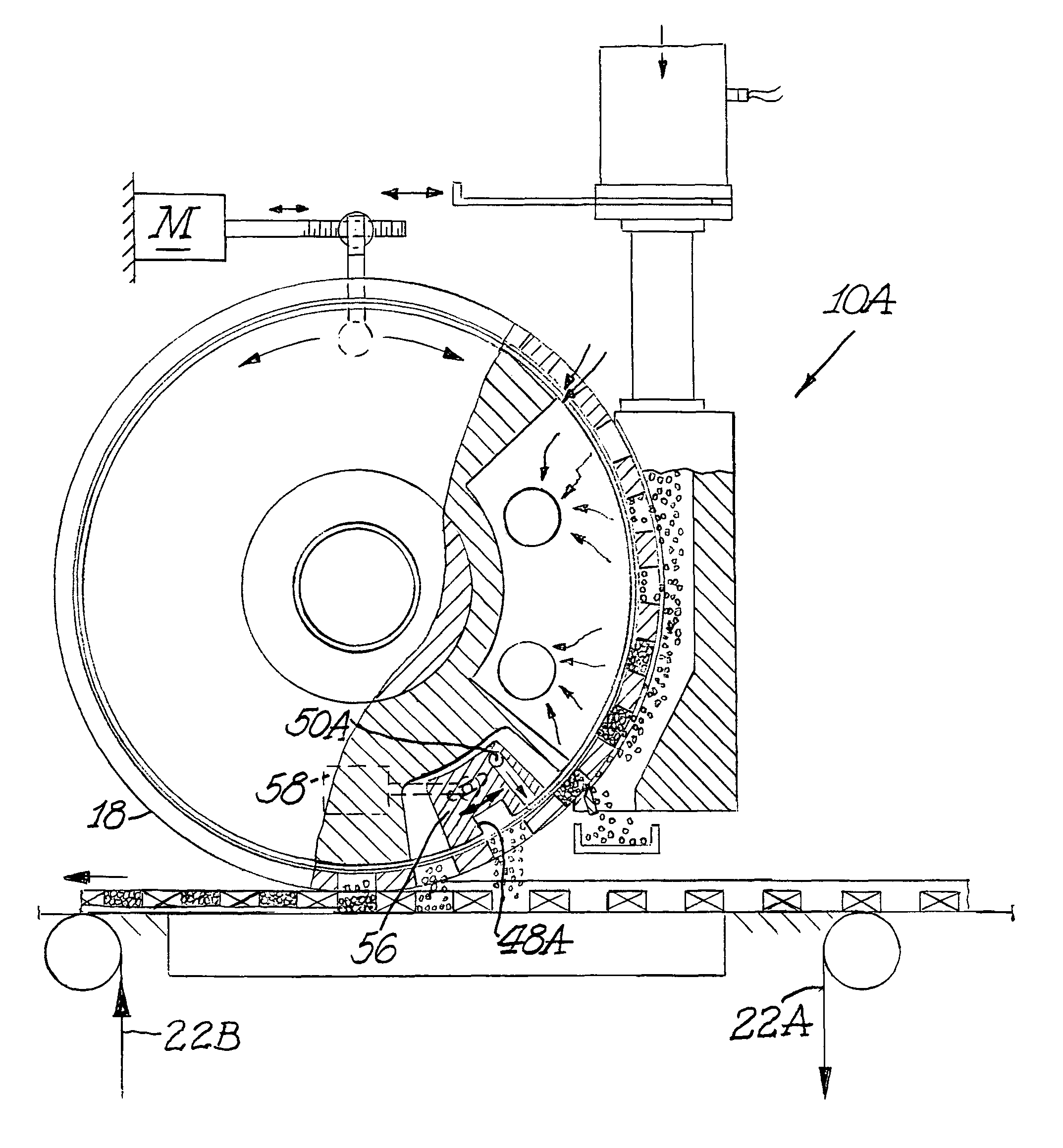
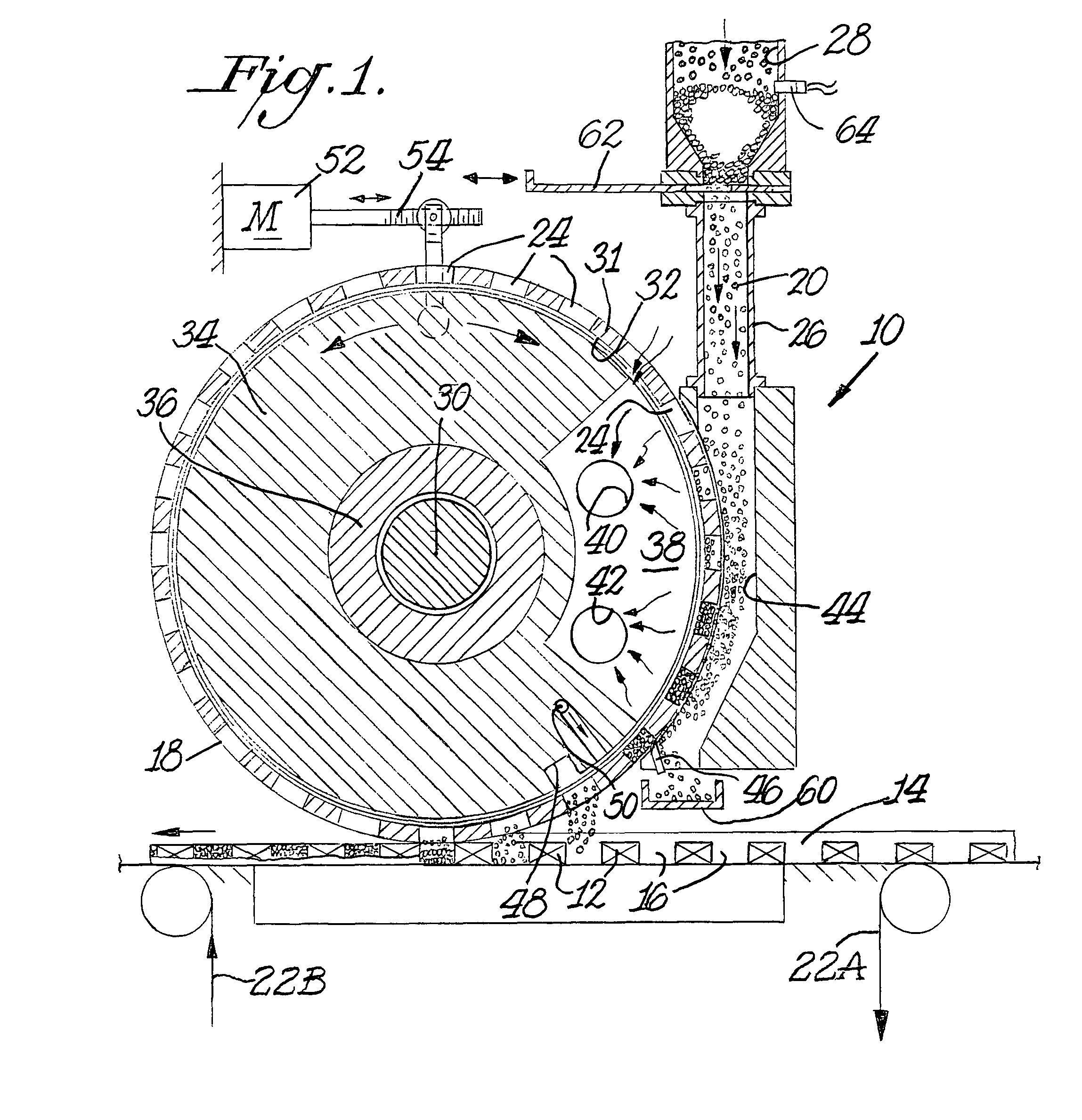
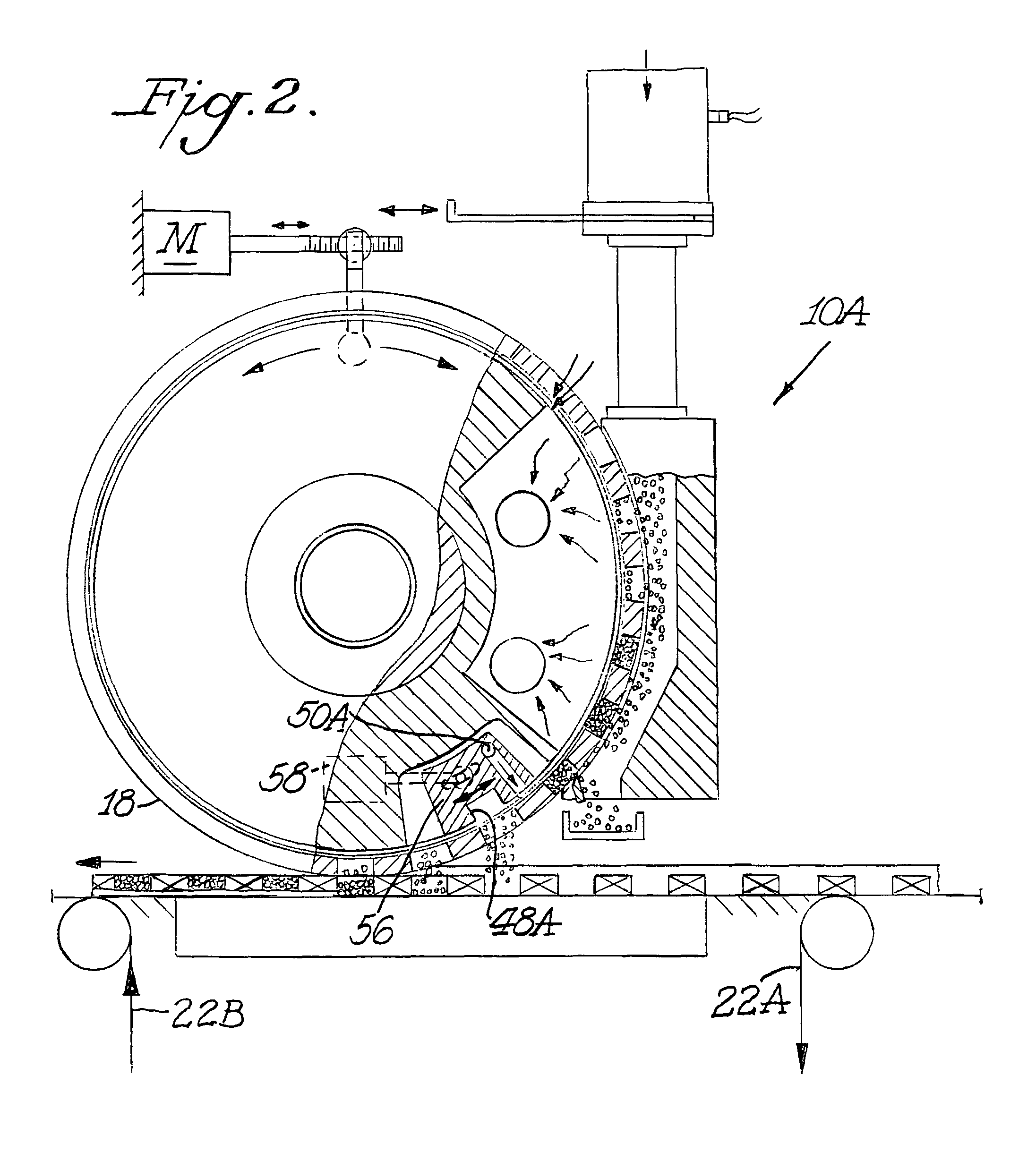
[0019]The present invention provides a system useful for transferring accurately metered volumes of particles to cavities in an article or articles being produced at a high rate during mass production of the articles. The system includes at least one applicator wheel which rotates around a central adjustable vacuum manifold including at least one vacuum chamber. A series of pockets are defined along an outer circumferential surface of the applicator wheel between the outer periphery of the wheel and a perforated band or screen that is clamped against the inner periphery of the wheel, to both accurately meter and transfer predetermined amounts of granules or particles into cavities of one or more articles.

[0020]The drawings illustrate an assembly line for producing cigarette filter rods of spaced apart cellulose acetate plugs with cavities therebetween filled with particulate material and surrounded by plug wrap. Initially the paper wrapped around the filter rod is left open at the t...


PUM

PropertyMeasurementUnit
speedaaaaaaaaaa
vacuumaaaaaaaaaa
speedsaaaaaaaaaa

Abstract

A machine and process function to fill cavities with metered amounts of particulate material. An applicator wheel includes a series of equally spaced apart peripheral pockets each having a perforated bottom wall, and a vacuum manifold inside the wheel includes a vacuum chamber for supplying vacuum to the perforated bottom walls of the pockets as the wheel rotates. Particulate material from a filling chamber of such material outside the wheel is withdrawn into the pockets by the vacuum chamber. A downstream vacuum relief on the vacuum manifold functions to discharge particulate material from the pockets into the cavities at a predetermined discharge location on the wheel. Adjustment structure is connected to rotatably adjust the position of the vacuum manifold within the applicator wheel to thereby advance or retard the discharge location depending upon the speed of the machine.

Description

CROSS REFERENCE TO RELATED APPLICATION[0001]The present application claims the benefit of provisional application Ser. No. 60 / 809,558, filed May 31, 2006, for all useful purposes, and the specification and drawings thereof are included herein by reference.BACKGROUND OF THE INVENTION[0002]The present invention generally relates to methods and apparatus for accurately delivering precisely metered amounts of particulate material from an applicator wheel in a repetitive manner during high speed manufacture of particulate-filled articles of manufacture, and more particularly to precise and repetitive delivery of particulate material from an applicator wheel into spaces presented during the manufacture of plug-space-plug cigarette filters.[0003]Certain articles of manufacture such as carbon cigarette filters, individual-sized packets of granular food products or condiments, capsuled pharmaceuticals, ammunition and the like require repetitive placement of precisely metered charges of parti...

Claims


Application Information

Patent Timeline
Patent Type & Authority Patents(United States)
IPC IPC(8): B65B1/04
CPCB65B1/366A24D3/0225B65B1/36B65B1/30A24D3/02
Inventor SMITH, BARRY S.GARTHAFFNER, MARTIN T.ERCELEBI, AHMETSPIERS, STEVENSTRAIGHT, JEREMY
Owner PHILIP MORRIS USA INC
Why Eureka
Try Eureka