
Hand-held gas combustion apparatus

a gas combustion and hand-held technology, applied in the direction of burners, combustion types, combustion processes, etc., can solve the problems of static electricity sparks not being guaranteed to be generated on the flame nozzle, and the inability of the flame device to be ignited

Inactive Publication Date: 2010-12-14
FUJIFILM CORP
View PDF7 Cites 12 Cited by
  • Summary
  • Abstract
  • Description
  • Claims
  • Application Information

AI Technical Summary

Benefits of technology

Enables reliable ignition of the combustion apparatus without the need for additional supporting structures, reducing production costs and ensuring a stable static electricity spark for igniting the mixed combustion gas, while maintaining structural integrity and heat-insulating efficiency.

Problems solved by technology

In view of the above mentioned art, the conductive wire has to be extended and fastened at one side of the flame nozzle, but on some occasions the flame device has limited space and the conductive wire is not able to pass through the limited space, thus the flame device is not able to be ignited.
Even if the flame device has an sufficient space to allow the conductive wire pass through, the conductive wire may be in contact with the flame device and combustion heat from the flame nozzle is transferred to the flame device, so the insulating sleeve tube of the conductive wire is melted by the heat and a static electricity spark can not be ensured to be generated on the flame nozzle.

Method used


Image

  • Hand-held gas combustion apparatus
  • Hand-held gas combustion apparatus
  • Hand-held gas combustion apparatus

Examples


Embodiment Construction

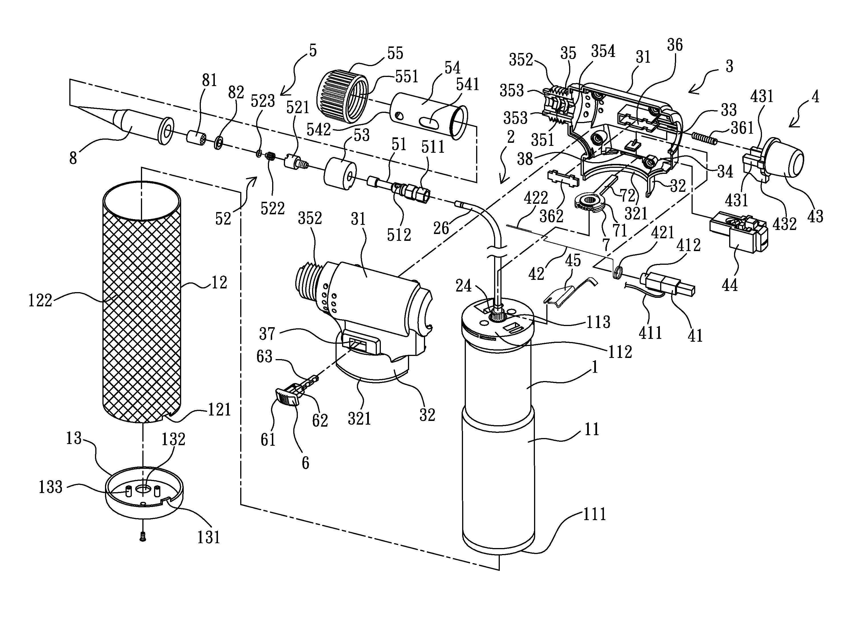
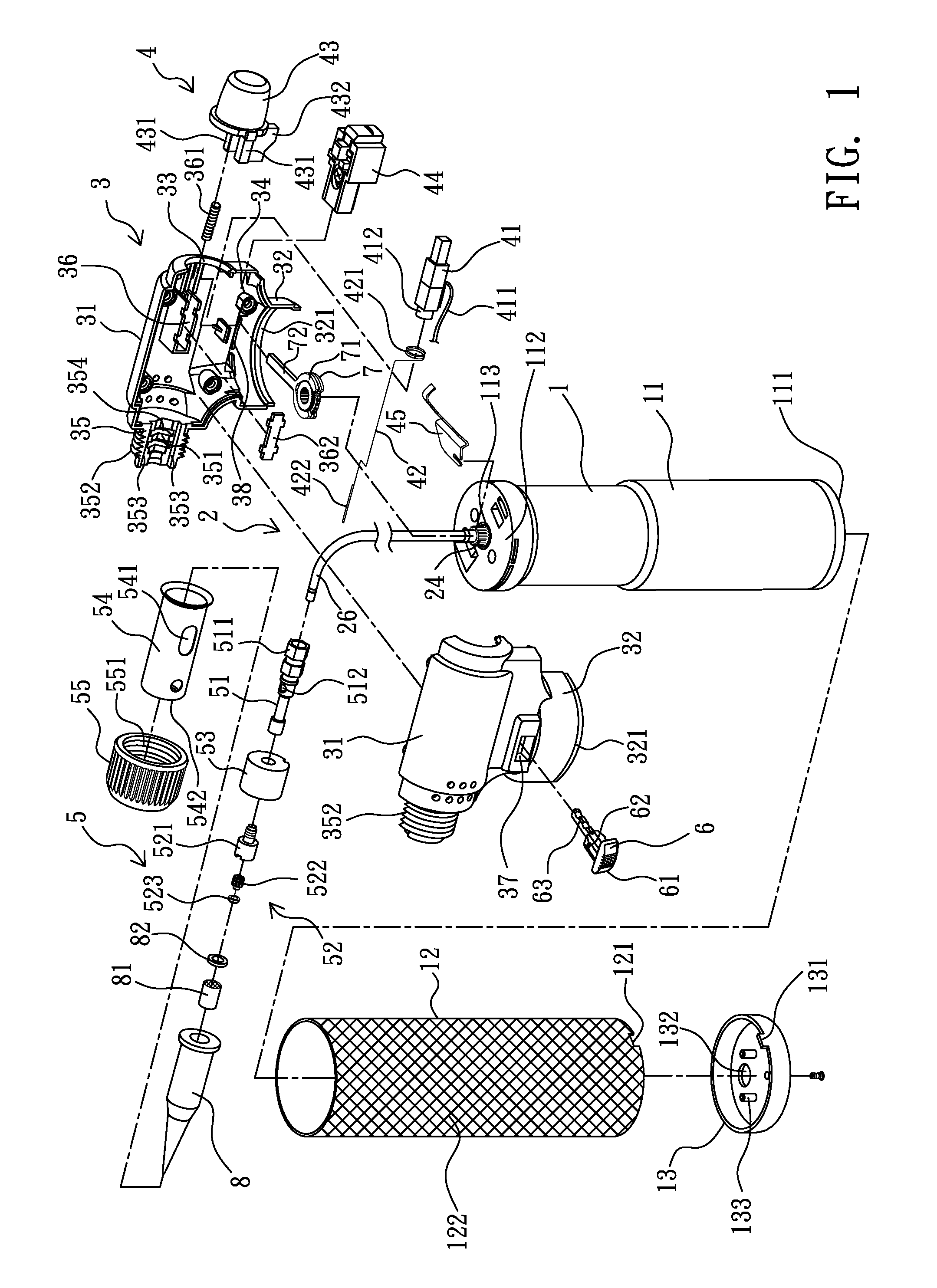
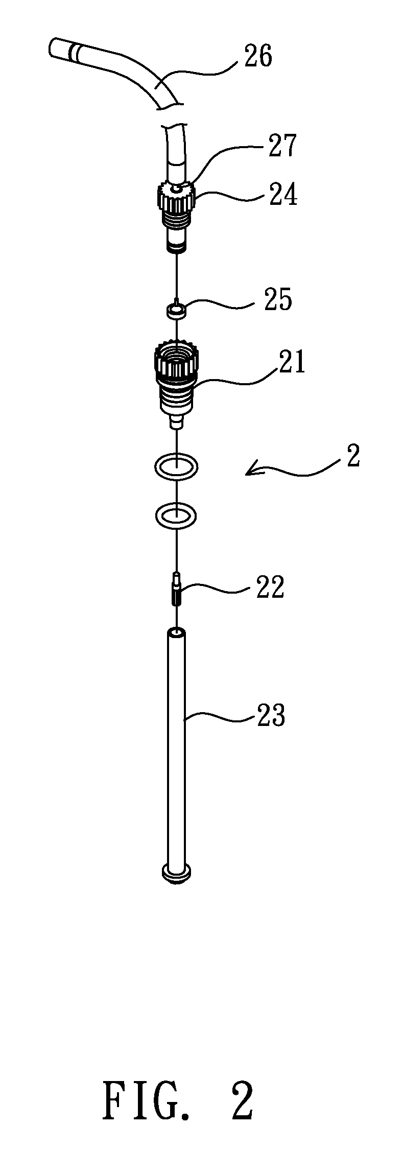
[0015]As shown from FIG. 1 to FIG. 2, the hand-held gas combustion apparatus provided by the present invention is composed by a gas storing tank 1, a gas discharging device 2, a housing 3, an ignition system 4 and a flame device 5.

[0016]The gas storing tank 1 is served to store liquefied gas, a tank bottom 111 provided on a bottom end of a tank body 11 of the gas storing tank 1 has a conventional gas filling nozzle (not shown) for being supplied with combustion fuel, and a tank top 112 provided at the top end of the tank body 11 has an opening 113 for receiving and positioning the gas discharging device 2. The difference between the gas storing tank 1 provided by the present invention and a conventional gas storing tank is that a foreign material can be provided on the tank body 11, e.g. an outer tube 12 made of aluminum alloy, a gap is defined between the outer tube 12 and the tank top 112 so when being connected to the housing 3, a connecting edge 321 extended from a connecting ri...


PUM


Abstract

The present invention relates to a hand-held gas combustion apparatus, comprises a gas storing tank, a gas discharging device, a housing, an ignition system and a flame device. The flame nozzle of the flame device and the metal sleeve tube are respectively in contact with the conductive wire and the electricity-guiding wire of the ignition system, so a static electricity spark is generated between the inner folding edge of the metal sleeve tube and the flame nozzle, so mixed combustion gas ejected from the flame nozzle is ignited, a gas combustion apparatus is therefore obtained, and the electricity-guiding wire is provided between the metal sleeve tube and the ignition system so the high-voltage static electricity can be guided back to the ignition system for forming a circuit. The present invention has overcome the disadvantages that a conductive wire of a conventional ignition system has to be provided at one side of the flame nozzle and the inconvenience of circuit design, and in the present invention there is no need of providing additional supporting racks for receiving and positioning the ignition system and the flame device.

Description

BACKGROUND OF THE INVENTION[0001]1. Field of the Invention[0002]The present invention relates to a gas combustion apparatus, more particularly to a hand-held gas combustion apparatus.[0003]2. Description of Related Art[0004]Fire is a must-have matter in human being's daily life, with fire we can cook food, have lights, even operating casting, melting or welding metals. Take a canned gas for instance, no matter the canned gas is served to fill a lighter for lightening or is connected to a portable gas burner for cooking food; thus the convenience of using a canned gas is provided, and the canned gas is easy to be carried and stored. So far the canned gas still plays an important part in daily life.[0005]Due to the convenience of using a canned gas, two kinds of gas combustion tools are both seen in the marketplace so a user can make his own decision. The U.S. Pat. No. 5,466,149 (corresponding to the Taiwan Utility Patent No. 110192) and the U.S. Pat. No. 5,564,919 (corresponding to t...

Claims


Application Information

Patent Timeline
Patent Type & Authority Patents(United States)
IPC IPC(8): F23D14/72F23Q1/04
CPCF23D14/28F23D14/38F23Q3/002
Inventor TSAI, CHIH-LIN
Owner FUJIFILM CORP
Learn More