Double-end fiber optic security system for sensing intrusions
What is Al technical title?
Al technical title is built by PatSnap Al team. It summarizes the technical point description of the patent document.
a security system and fiber optic technology, applied in the direction of optical radiation measurement, fire alarm radiation actuation, instruments, etc., can solve the problems of system not being suited to a wide geographical area security system, not using fiber optics,
Active Publication Date: 2010-12-14
WOVEN ELECTRONICS
View PDF30 Cites 20 Cited by
Summary
Abstract
Description
Claims
Application Information
AI Technical Summary
This helps you quickly interpret patents by identifying the three key elements:
Problems solved by technology
Method used
Benefits of technology
Problems solved by technology
However, the system does not use fiber optics, requires electrical power at the location, and is generally not suited for a wide area security system.
However, this system requires physical connection of the optic fiber to the appliance and the system is not suitable for detecting events in a wide geographical area.
Here again, the system requires physical connection to the moveable part of the fence and the fiber optic cable requires electrical power at the location, and is generally not suitable for wide geographical areas.
Not only do the above security systems and sensors require a physical connection between the optic fiber and the moveable member, but the systems require electrical power at the location sought to be protected making them wholly unsuitable for many security applications, including wide geographical area systems.
More importantly, no provision is made for identifying the location of an intrusion event where large numbers of sensors are utilized.
Method used
Image
Click on the blue label to locate the original text in one second.
Reading with bidirectional positioning of images and text.
Examples
Embodiment Construction
[0042]Referring now to the drawings, the invention will now be described in more detail.
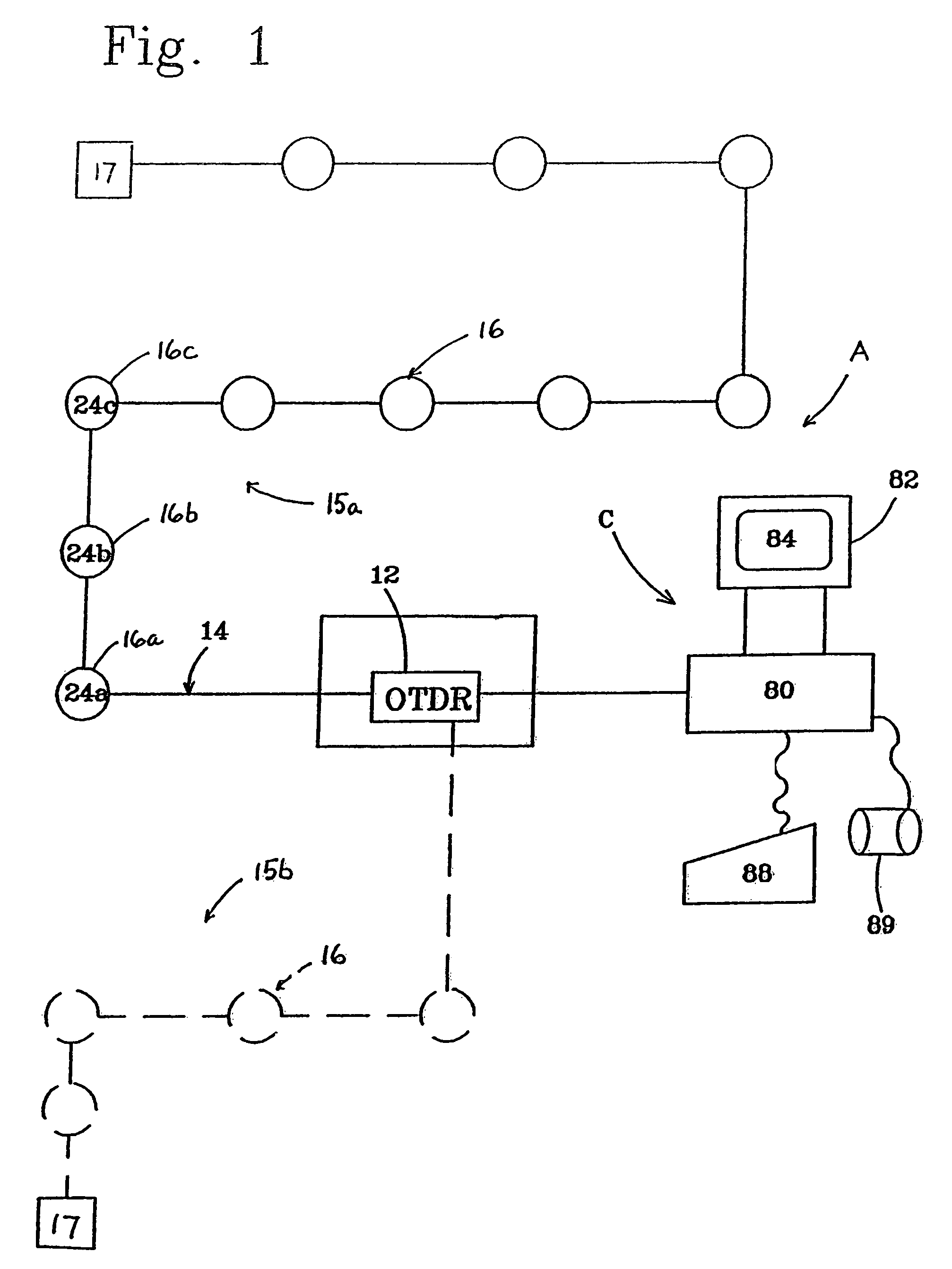
[0043]As can best be seen in FIG. 1, an optical fiber security system, designated generally as A, is illustrated. The security system includes a remote processor, designated generally as 10, for processing an intrusion signal to determine the occurrence, type or cause, and location of the intrusion. The processor may, for example, include an optical time domain reflectometer (OTDR) 12, of the type routinely utilized to monitor maintenance of fiber optic network systems, coupled with a computer and resident software for assessing the nature of the intrusion based on stored “signature” intrusion signal data. Typically, the OTDR is used to sense a fiber breakage, water seepage, irregular bends, or other defects in one or more optical fibers of the fiber network along the routing path of the network. For example, in large municipalities it is not uncommon for there to be 1,000 miles of fibers in an o...
PUM
Abstract
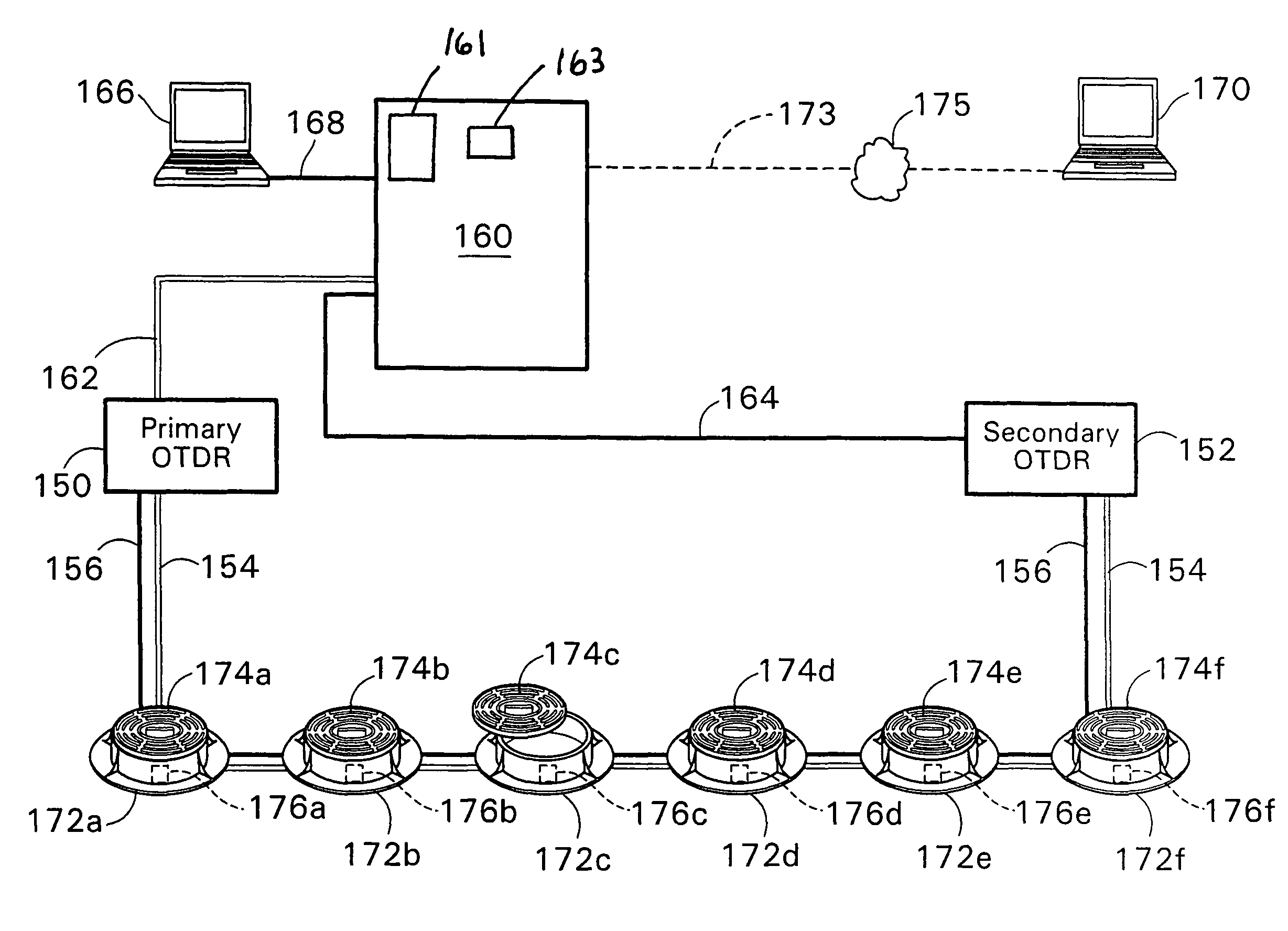
A security system is disclosed for detecting intrusions at a plurality of predetermined locations having moveable closure members. The system comprises a plurality of intrusion sensors disposed at the locations for detecting movement of the closure members. Primary and secondary optical fiber sensor lines are routed through the intrusion sensors, and primary and secondary scanning units pulse signals along the sensor lines and receive reflected signals back from the sensor lines. A processor processes the reflected signals to determine if a reflection and / or attenuation change has occurred in a reflected pulse signal signifying a prescribed level of unauthorized intrusion activity which matches a signature intrusion signal. In the event of a cut through in the sensor lines, the primary sensor line monitors the sensors downstream of the break, and the secondary sensor line is activated to monitor the sensors upstream of the break.
Description
[0001]This application is related to and claims priority from U.S. Provisional Application No. 60 / 456,687, filed Mar. 15, 2003, entitled “Fiber Optic Security System For Sensing the Intrusion Of Secured Locations,” now abandoned; U.S. non-provisional application Ser. No. 10 / 429,602, filed May 5, 2003, entitled “Fiber Optic Security System For Sensing Intrusion Of Secured Locations;” PCT application no. PCT / US2004 / 013494, filed May 3, 2004, entitled “Fiber Optic Security System For Sensing The Intrusion Of Secured Locations;” now International Publication Number WO 2004 / 100095 A2, published Nov. 18, 2004; U.S. non-provisional application Ser. No. 10 / 555,534, filed May 10, 2006, entitled “Fiber Optic Security System For Sensing The Intrusion Of Secured Locations;” U.S. Provisional Application No. 60 / 626,197, filed Nov. 9, 2004, entitled “Vehicle Denial Security System;” U.S. non-provisional application Ser. No. 11 / 083,038, filed Mar. 17, 2005, entitled “Apparatus And Method For A Comp...
Claims
Application Information
Patent Timeline
Application Date:The date an application was filed.
Publication Date:The date a patent or application was officially published.
First Publication Date:The earliest publication date of a patent with the same application number.
Issue Date:Publication date of the patent grant document.
PCT Entry Date:The Entry date of PCT National Phase.
Estimated Expiry Date:The statutory expiry date of a patent right according to the Patent Law, and it is the longest term of protection that the patent right can achieve without the termination of the patent right due to other reasons(Term extension factor has been taken into account ).
Invalid Date:Actual expiry date is based on effective date or publication date of legal transaction data of invalid patent.