Loading tray and thin plate container

a technology of loading tray and thin plate, which is applied in the direction of tray containers, packaging goods types, transportation and packaging, etc., can solve the problems of easy breakage and thinness of each thin plate, and achieve the effect of reliably supporting, carrying safely, and supporting reliably

Inactive Publication Date: 2010-12-21
MIRAIAL CO LTD
View PDF14 Cites 15 Cited by
  • Summary
  • Abstract
  • Description
  • Claims
  • Application Information

AI Technical Summary

Benefits of technology

[0038]As described above in detail, the loading tray and the thin plate container of the present invention exert the following effects.
[0039]With the loading tray according to the first invention, since the housing spaces are formed by stacking the plural loading trays, and the thin plate is sandwiched and supported in each of the housing spaces by the first loading portion and the second loading portion, and the thin plates are housed in these housing spaces and are supported reliably even when the loading tray is placed upside-down, the thin plates can be carried safely.
[0040]Since the loading projection portion is provided on either or both of the first loading portion and / or the second loading portion and thrusts and supports the thin plate housed in the housing space, the thin plate can be supported reliably and can be carried safely. After carriage, the loading trays can be separated from one another, and each tray can be used as a tray for carriage.
[0041]Since the loading projection portion is formed in a web state on the entire loading surface of the first loading portion and / or the second loading portion to thrust and support the thin plate uniformly, the thin plate can be carried safely. In particular, in a case of a thin and flexible thin plate, it can be supported reliably and can be carried safely.
[0042]Since the conduit is provided to each loading tray to suck air from the outside, and the thin plate is adsorbed and constrained to the loading projection portion, the thin plate can be constrained reliably and can be carried safely.
[0043]Since the communication cutouts are provided at the web loading projection portion to communicate with plural spaces partitioned by the loading projection portion and the thin plate, and air in the communicated plural spaces is sucked via the conduit to adsorb and constrain the thin plate to the loading projection portion, each space partitioned by the loading projection portion functions as a sucker, and thus the thin plate can be constrained reliably and can be carried safely.

Problems solved by technology

Thus, each thin plate gets extremely thin and is easy to break regardless of its dimension.

Method used


Image

  • Loading tray and thin plate container
  • Loading tray and thin plate container
  • Loading tray and thin plate container

Examples


first embodiment

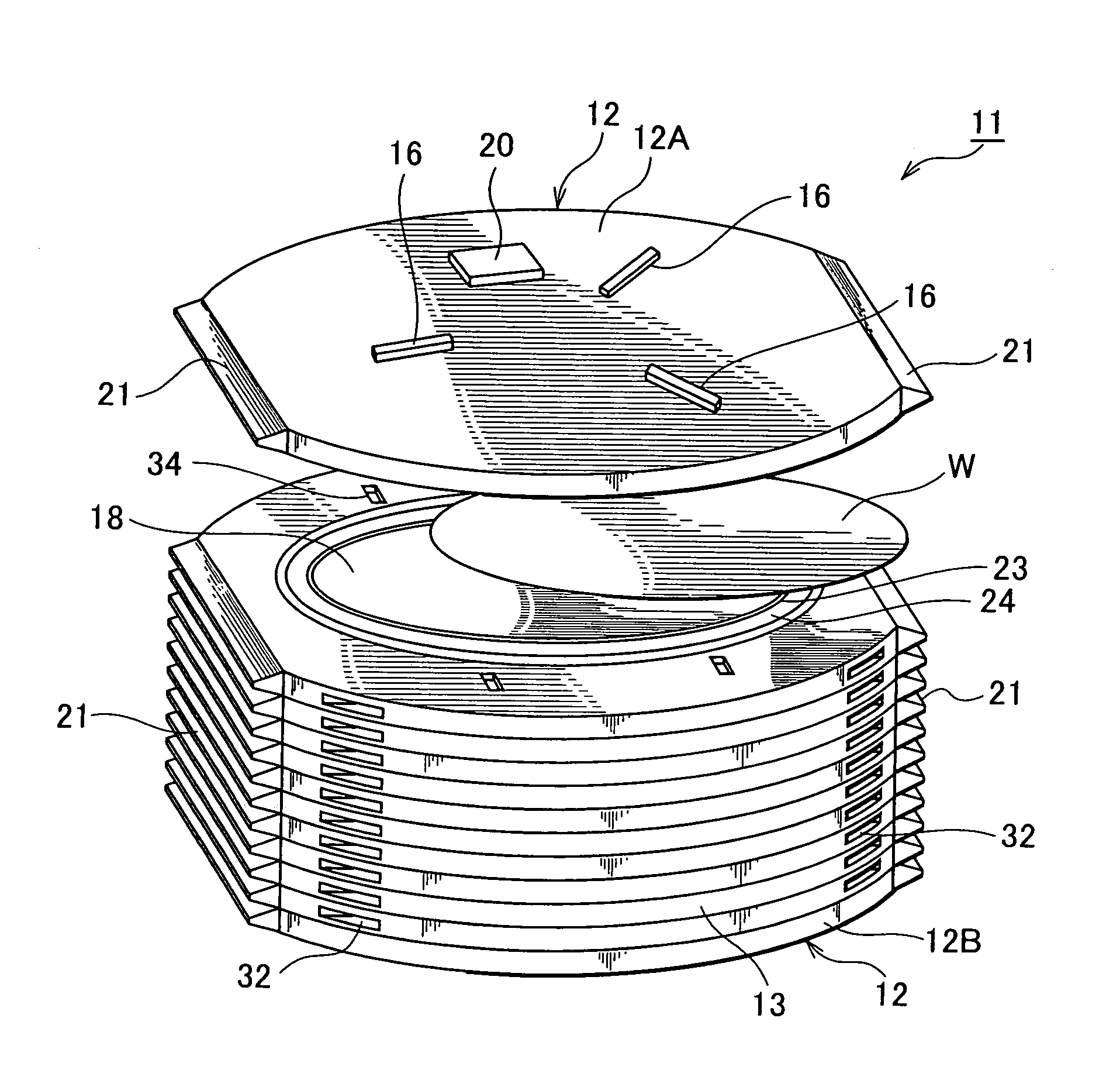
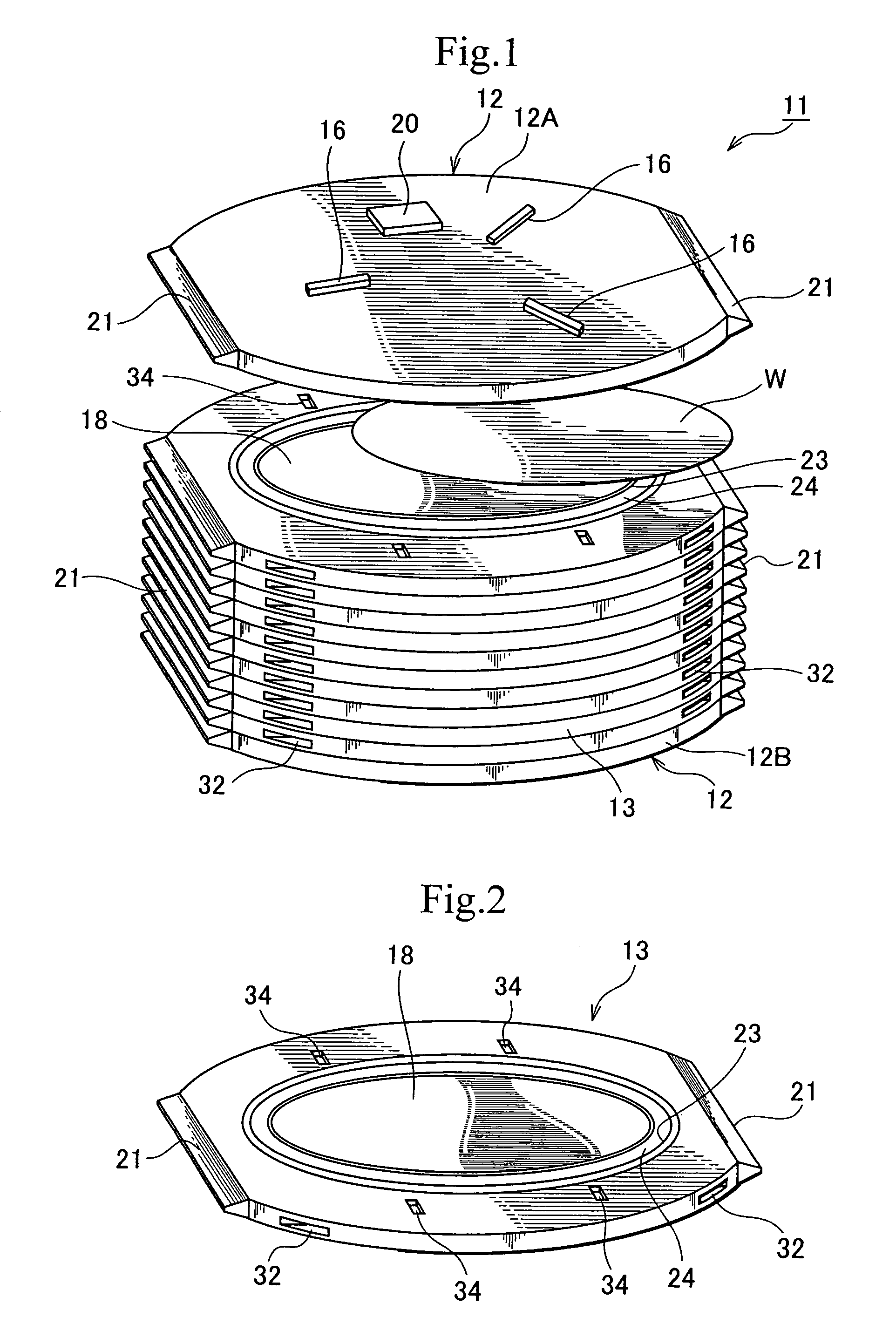
[0124]As shown in FIG. 1, a thin plate container 11 is mainly constituted by a pair of base trays 12, loading trays 13 inserted between respective base trays 12, and a coupling / releasing means 14 (refer to FIG. 5) for coupling the adjacent loading trays 13 and coupling the base tray 12 with the loading tray 13 and releasing the coupling.

[0125]The base trays 12 are trays that protect the top end surface and the bottom end surface of the plurally stacked loading trays 13 and that are engaged with a mechanical apparatus (not shown) for performing processing such as polishing of a semiconductor wafer W. Each base tray 12 is formed approximately in a disk shape. On the rim of each base tray 12, after-mentioned grips 21 are provided at two positions opposed to each other. The base trays 12 consist of an upper base tray 12A and a lower base tray 12B and are provided at the upper and lower end portions of one or plural stacked loading trays 13. On the upper side of the upper base tray 12A, ...

second embodiment

[0181]Next, a second embodiment of the present invention will be described. As the entire structure of a thin plate container in the present embodiment is approximately the same as that of the thin plate container 11 in the aforementioned first embodiment, the same members are labeled with identical numerals, and the description of them is omitted.

[0182]The thin plate container in the present embodiment is characterized by comprising a communication cutout 44 and a conduit 45, as shown in FIGS. 8 and 9.

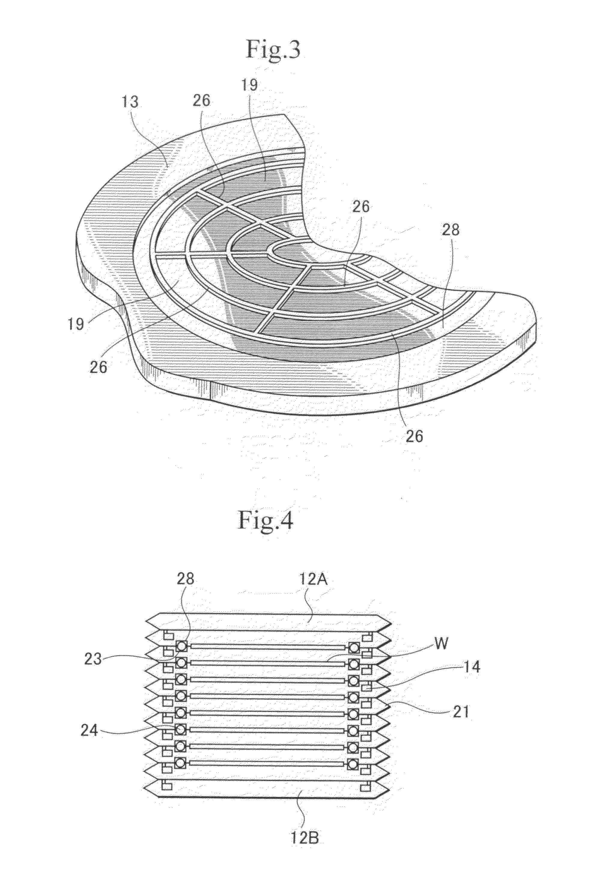
[0183]The communication cutout 44 is a cutout to communicate with plural suction spaces partitioned by the web loading projection portion 26 provided on the second loading portion 19 of the loading tray 13 and the semiconductor wafer W when the loading projection portion 26 and the semiconductor wafer W abut to each other. Accordingly, air in one suction space partitioned by the loading projection portion 26 is sucked from the conduit 45, so that air in suction spaces partitioned by t...

third embodiment

[0203]Next, a third embodiment of the present invention will be described. As the entire structure of a thin plate container in the present embodiment is approximately the same as that of the thin plate container 11 in the aforementioned first embodiment, the same members are labeled with identical numerals, and the description of them is omitted.

[0204]The thin plate container in the present embodiment is characterized by forming the flat surface shape of a loading tray 51 in an approximately square shape, as shown in FIGS. 13 to 17. It is also characterized by comprising a positioning cut-out 52, a tray positioning pin 53, and a tray positioning hole 54. It is noted that the tray positioning pin 53 and the tray positioning hole 54 constitute a displacement prevention means for preventing mutual displacement at the time of coupling of the loading trays 51.

[0205]The flat surface shape of the loading tray 51 is formed in an approximately square shape, as shown in FIGS. 13 to 15. On th...


PUM


Abstract

A loading tray 13 supports at least one thin plate safely and reliably. It comprises a first loading portion 18, provided on one side thereof, on which at least one thin plate is loaded; a second loading portion 19, provided on the other side thereof, fitted to the first loading portion 18 of adjacent loading tray 13 to form a housing space sealed off from the external environment, for sandwiching the thin plate within the housing space, and for loading the thin plate on the loading tray when the loading tray is placed upside-down; a hook 30, provided on one side thereof, for coupling with an adjacent loading tray 13; and a hook locking mechanism 31, provided on the other side thereof, for coupling with the hook 30 of an adjacent loading tray 13. As many loading trays 13 as the number of the thin plate is stacked to constitute a thin plate container 11. The thin plate container 11 can support the thin plate from both upper and lower sides.

Description

TECHNICAL FIELD[0001]The present invention relates to a loading tray and a thin plate container for supporting thin plates for electronic devices such as semiconductor wafers, magnetic recording medium disks, optical recording medium disks, glass substrates for liquid crystal panels, film substrates for flexible display apparatuses, and so on for carriage, storage, processing, etc.BACKGROUND ART[0002]Recently, there is a demand for further thinning of a thin plate for an electronic device such as a semiconductor wafer, etc. Thus, each thin plate gets extremely thin and is easy to break regardless of its dimension.[0003]Also, even in a case where the plate thickness does not change, enlargement of the external diameter leads to a thin-plate trend relatively from the viewpoint of the ratio between the plate thickness and the external diameter.[0004]As a container for housing, storing, and loading such an extremely thin plate, a multistage type housing cassette described in Reference D...

Claims


Application Information

Patent Timeline
Patent Type & Authority Patents(United States)
IPC IPC(8): B65D85/00
CPCH01L21/67294H01L21/67346H01L21/67379H01L21/673H01L21/683
Inventor HYOBU, YUKIHIRO
Owner MIRAIAL CO LTD
Why Eureka
Try Eureka