Method for performing a coplanar connection between a conductor and a contact on an implantable lead

Inactive Publication Date: 2010-12-28
MEDTRONIC INC
View PDF111 Cites 99 Cited by
  • Summary
  • Abstract
  • Description
  • Claims
  • Application Information

AI Technical Summary

Benefits of technology

[0006]An implantable lead with a coplanar coupling for connecting a conductor to a contact to reduce conductor bending moments to improve lead reliability. The implantable lead comprises a lead body having a proximal end and a distal end, at least one conductor, at least one contact carried on the proximal end, at least one contact carried on the distal end, and at least one coupling. The lead body has an exterior surface. The conductor is contained in the lead body and extends from the lead proximal end to the distal end. The conductor is also electrically insulated. The contact carried on the proximal end is electrically connected to the conductor. The coupling has a conductor coupling and a contact coupling. The conductor coupling is placed over the conductor and attached to the conductor. The contact coupling exits the lead body and has a weld to connect the contact coupling to the contact. The contact coupling is configured to exit the conductor lumen and mate with the contact while retaining the conductor coplanar to the lead body.
[0007]Another aspect of the present invention provides for an implantable lead with a coplanar coupling for connecting a conductor to a contact to reduce conductor bending moments to improve lead reliability. The implantable lead comprises a lead body having a proximal end, a distal end, at least

Problems solved by technology

Conductors manufactured from low impedance materials such as silver make forming a connection with good mechanical properties challenging because silver has substantially less tensile strength than a more common conductor material such as MP35N.
Additionally, silver content in the weld joint

Method used


Image

  • Method for performing a coplanar connection between a conductor and a contact on an implantable lead
  • Method for performing a coplanar connection between a conductor and a contact on an implantable lead
  • Method for performing a coplanar connection between a conductor and a contact on an implantable lead

Examples


Embodiment Construction

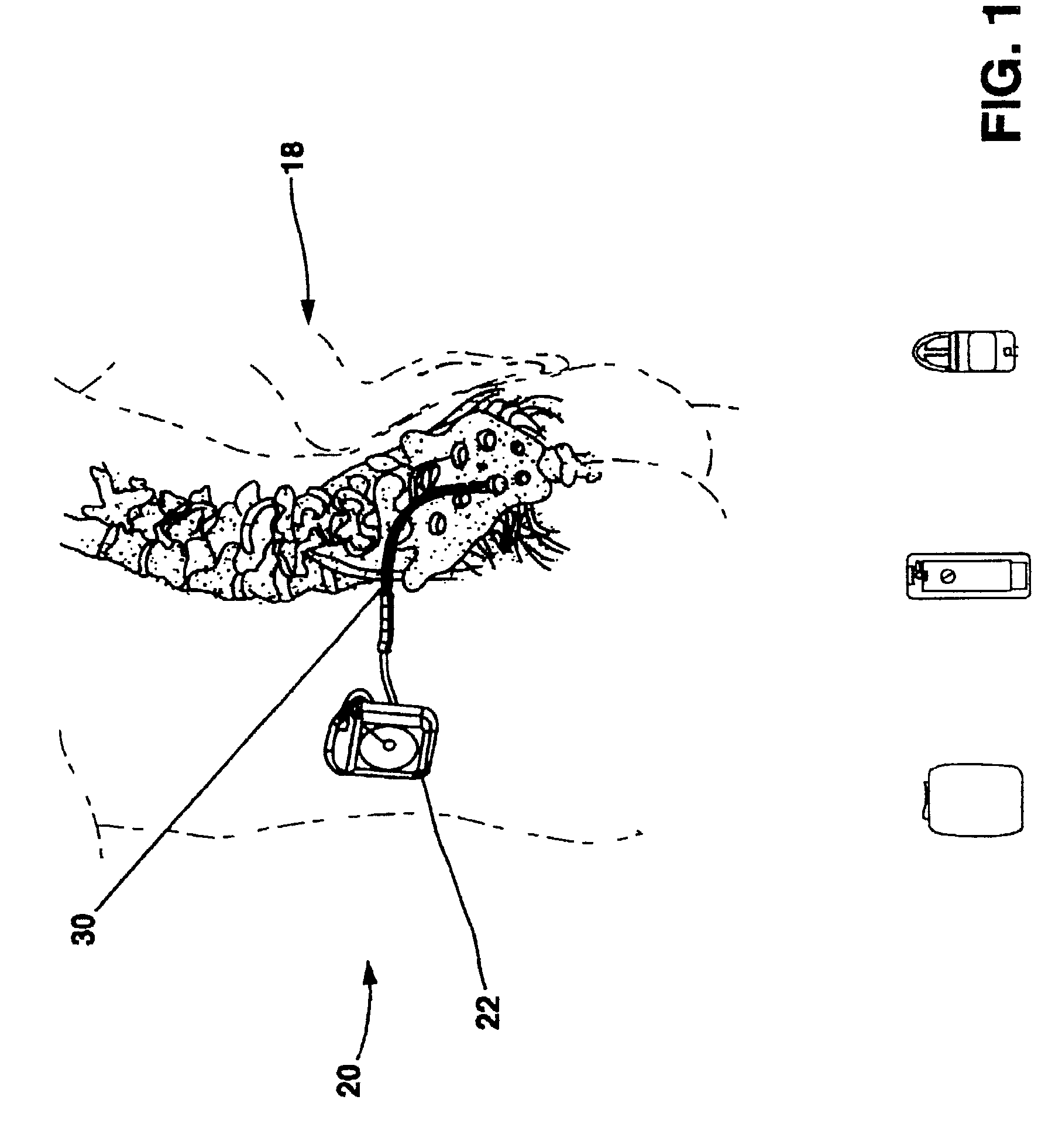
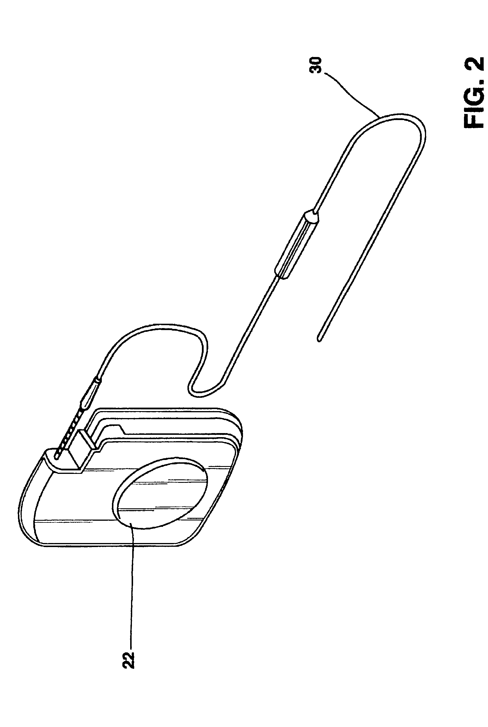
[0038]FIG. 1 shows a general environmental view of an implantable neurostimulation system embodiment and FIG. 2 shows a neurostimulation system embodiment. Neurostimulation systems are used to treat conditions such as pain, movement disorders, pelvic floor disorders, gastroparesis, and a wide variety of other medical conditions. The neurostimulation system 20 includes a neurostimulator 22 such as an Itrel II® Model 7424 or an Itrel 3® Model 7425 available from Medtronic, Inc. in Minneapolis, Minn., a stimulation lead extension 24, and a stimulation lead 30. The neurostimulator 22 is typically implanted subcutaneously in the patient's body 18 at a location selected by the clinician. The stimulation lead 30 is typically fixed in place near the location selected by the clinician using a device such as the adjustable anchor. The implantable lead 30 can be configured as a neurological stimulation lead, a neurological sensing lead, and a combination of both as a neurological stimulation a...


PUM


Abstract

An implantable lead for a medical device with a coplanar coupling for connecting a conductor to a contact reduces conductor bending moments to improve lead reliability. The implantable lead comprises a lead body having a proximal end and a distal end, at least one conductor, at least one contact carried on the proximal end, at least one contact carried on the distal end, and at least one coupling. The lead body has an exterior surface. The conductor is contained in the lead body and extends from the lead proximal end to the distal end. The conductor is also electrically insulated. The contact carried on the proximal end is electrically connected to the conductor. The coupling has a conductor coupling and a contact coupling. The conductor coupling is placed over the conductor and attached to the conductor. The contact coupling exits the lead body and has a weld to connect the contact coupling to the contact. The contact coupling is configured to exit the conductor lumen and mate with the contact while retaining the conductor coplanar to the lead body.

Description

CROSS REFERENCES[0001]This application is a continuation in part of application Ser. No. 10 / 131,106, to Pardo et. al. filed Apr. 22, 2002.BACKGROUND OF THE INVENTION[0002]This disclosure relates to medical devices and more particularly to an implantable lead.[0003]The medical device industry produces a wide variety of electronic and mechanical devices for treating patient medical conditions such as pacemakers, defibrillators, neuro-stimulators and therapeutic substance delivery pumps. Medical devices can be configured to be surgically implanted or connected externally to the patient receiving treatment. Clinicians use medical devices alone or in combination with therapeutic substance therapies and surgery to treat patient medical conditions. For some medical conditions, medical devices provide the best and sometimes the only therapy to restore an individual to a more healthful condition and a fuller life. One type of medical device is an implantable neurological stimulation system t...

Claims


Application Information

Patent Timeline
IPC IPC(8): H01R9/00H05K3/00A61N1/05
CPCA61N1/05Y10S439/909Y10T29/49151Y10T29/49181Y10T29/49117
Inventor COLE, MARY LEE
Owner MEDTRONIC INC
Why Eureka
Try Eureka