Honeycomb segment

a honeycomb and segment technology, applied in the field of honeycomb segment, can solve the problems of low strength against thermal stress and rapid increase in pressure loss in the dpf, and achieve the effects of reducing porosity and pore size variance, uniform thickness, and improving bonding strength

Active Publication Date: 2010-12-28
NGK INSULATORS LTD
View PDF9 Cites 54 Cited by
  • Summary
  • Abstract
  • Description
  • Claims
  • Application Information

AI Technical Summary

Benefits of technology

[0008]The present invention aims to provide a honeycomb segment having an effect in improving bonding strength and alleviating thermal stress caused upon soot combustion by inhibiting clogging of cells to improve trapping performance and by linearly forming the outer walls to have a uniform thickness.
[0016]By linearly forming the outer walls having a uniform thickness, flowability of the material for the outer peripheral portion upon forming a segment becomes uniform to reduce a variance in porosity and pore size of the outer walls. This enables to obtain a uniform anchor effect of the bonding material upon bonding honeycomb segments, thereby improving bonding strength. In addition, by linearly forming the outer walls having a uniform thickness, the bonding width of the bonding material layer upon bonding honeycomb segments becomes constant to reduce a variance in pressure loss and a variance in a thermal stress absorption effect by the bonding material. In addition, a crack inhibition effect can be improved against local thermal stress caused upon soot combustion.

Problems solved by technology

Such clogging of cells causes rapid increase in pressure loss in the DPF.
Therefore, when PM is combusted and removed by performing post injection when PM has deposited in the DPF, thermal stress concentrates in a part of the thin intersection portion to easily cause breakage.
However, the problem of low strength against thermal stress still remains.

Method used


Image

  • Honeycomb segment
  • Honeycomb segment
  • Honeycomb segment

Examples


example

[0053]Hereinafter, the present invention will be described in more detail on the basis of Examples. However, the present invention is by no means limited to these Examples.

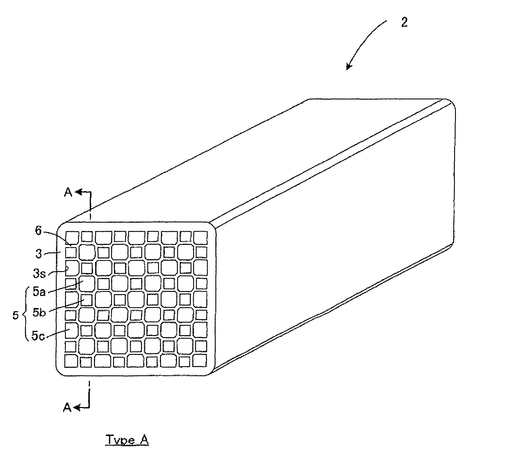
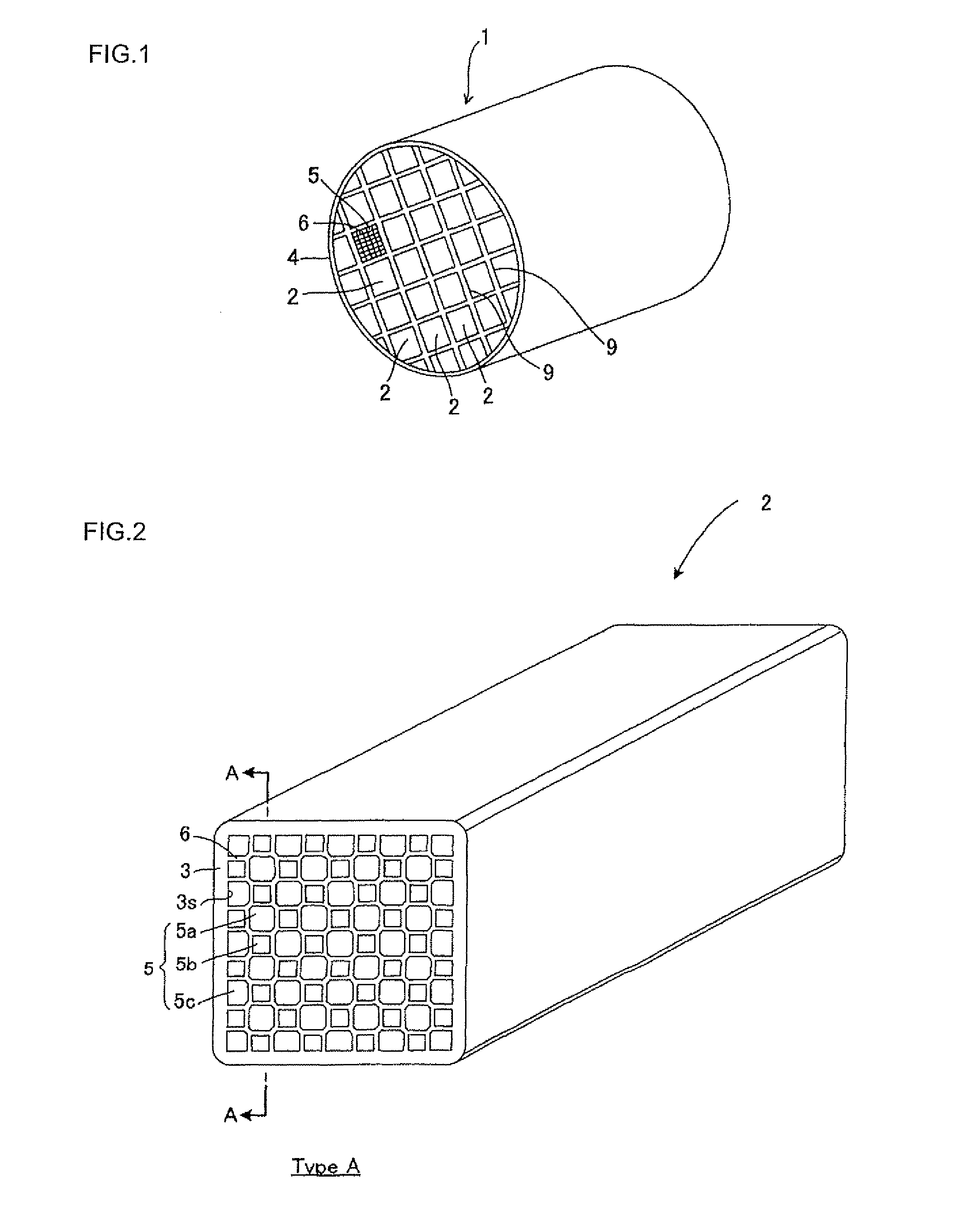
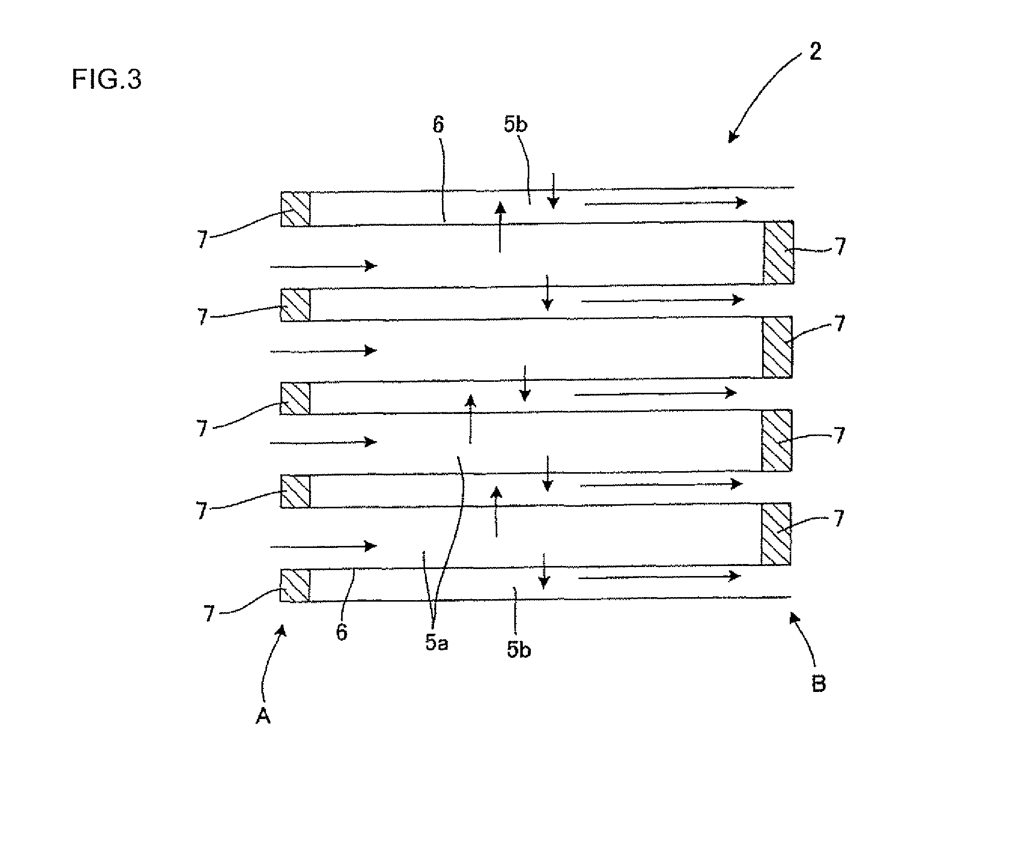
[0054]The honeycomb segment of the aforementioned Type A is prepared, and, as shown in FIG. 7, the bonding strength of the honeycomb segment was checked from the degree of change of the outer wall (X % of the thickness of the outer wall (wall thickness)) with respect to the designed value (standard thickness) W0. As shown in FIG. 8, the bonding strength was measured by four-point bending strength by preparing two honeycomb segments bonded together with a bonding material, supporting the honeycomb segments in the support portions, and applying pressure with an autograph so that stress was applied on the bonding portion.

[0055]The bonding strength ratio with respect to the variance in thickness is shown in FIG. 9. As shown in FIG. 9, when the variance in thickness exceeds 15%, the bonding strength is reduced. That is...


PUM

PropertyMeasurementUnit
thicknessaaaaaaaaaa
areaaaaaaaaaaa
cell structureaaaaaaaaaa

Abstract

A honeycomb segment containing outer walls and porous partition walls disposed inside the outer walls has a structure where first cells each open in one end portion on one side and plugged in the other end portion on the other side and second cells each plugged in one end portion on one side and open in the other end portion on the other side are alternately disposed, a cross-sectional area of the first cells in a cross section cut along a plane perpendicular to a longitudinal direction of the cells is larger than that of the second cells, and the first cells and the second cells are alternately disposed in a first direction and in a second direction perpendicular to the first direction in the cross section, and the outer walls are linearly formed so as to have a uniform thickness except for corner portions.

Description

TECHNICAL FIELD[0001]The present invention relates to a honeycomb segment. More specifically, the present invention relates to a honeycomb segment capable of inhibiting clogging by particulate matter or the like on the end face on the fluid inflow side and maintaining high strength.BACKGROUND ART[0002]In consideration of influences on the environment, there is an increased need for removing particulate matter and harmful substances in exhaust gas from an internal combustion engine, a boiler, and the like. In particular, regulations regarding removal of particulate matter (hereinafter referred to from time to time as “PM”) discharged from a diesel engine tends to be strengthened on a global basis, and use of a honeycomb filter is attracting attention as a trapping filter (hereinafter referred to from time to time as a “DPF”) for removing PM, and various kinds of systems have been proposed. In the aforementioned DPF, generally a plurality of cells functioning as fluid passages and eac...

Claims


Application Information

Patent Timeline
Patent Type & Authority Patents(United States)
IPC IPC(8): B32B3/12
CPCB01D46/247B01D46/2474C04B35/185C04B35/195C04B35/565C04B35/584C04B38/0006C04B38/0054C04B38/0074B01D46/2459Y10T428/24149B01D2046/2481B01J35/04C04B2111/00793C04B2111/0081B01D46/2466B01D46/249B01D46/2484B01D46/2482B01D46/2478
Inventor YAMASHITA, MASATAKA
Owner NGK INSULATORS LTD
Why Eureka
Try Eureka