Laminar article for electrical use and a method and machine for producing said article

a technology for laminar articles and electrical use, applied in the direction of dynamo-electric machines, other manufacturing equipment/tools, cores/yokes, etc., can solve the problems of insufficient effectiveness of laminar structures provided with the aforedescribed laminations, inability to ensure the maintenance of a correct spiraling angle and/or compensation for all laminations, and complex (in particular from the machine viewpoint)

Active Publication Date: 2010-12-28
CORRADA SPA
View PDF9 Cites 18 Cited by
  • Summary
  • Abstract
  • Description
  • Claims
  • Application Information

AI Technical Summary

Benefits of technology

[0010]Within the scope of this technical aim, an object of the invention is to provide a laminar article, a method and a machine in which the superposed laminations are in direct mutual contact, to hence eliminate the air spaces between adjacent laminations; in this manner both the electrical characteristics of the structure and its mechanical and dimensional characteristics are improved, and with elimination of the undesired “springy effect”.
[0012]A further object of the invention is to provide a laminar article, a method and a machine in which spiralling and / or compensation can also be achieved with very small angles without the risk of the laminations not being able to maintain these angles (for example at their ends).

Problems solved by technology

However this structure presents numerous drawbacks, including in particular incorrectly coupling adjacent laminations together; in practice, because of the manner in which the fastener / seat pairs are formed, a small air space remains between the laminations of the lamellar structure, to impede correct lamination stacking, with consequent problems in the electrical behaviour of the lamellar structure, and in the definition of the overall dimensions of the structure itself, with the generation of a characteristic “springy” effect within the lamellar structure, and sometimes with incorrect spiraling rotation and / or compensation of the laminations relative to each other.
However the lamellar structures provided with the aforedescribed laminations have also proved to be insufficiently effective because the height of the fasteners must be in relation to the thickness of the laminations to ensure correct connection.
Moreover, with the aforedescribed traditional systems it has proved very complicated (in particular from the machine viewpoint) to achieve correct lamination spiraling and / or compensation.
However the rotations to be imposed on the laminations can also be very large (for example up to 180°) and in particular for very tall lamellar structures, i.e. composed of a large number of superposed laminations in which the offsetting between one and the next lamination is small, the traditional systems are unable to ensure maintenance of a correct spiraling angle and / or compensation for all laminations, for example at their ends.

Method used


Image

  • Laminar article for electrical use and a method and machine for producing said article
  • Laminar article for electrical use and a method and machine for producing said article
  • Laminar article for electrical use and a method and machine for producing said article

Examples


first embodiment

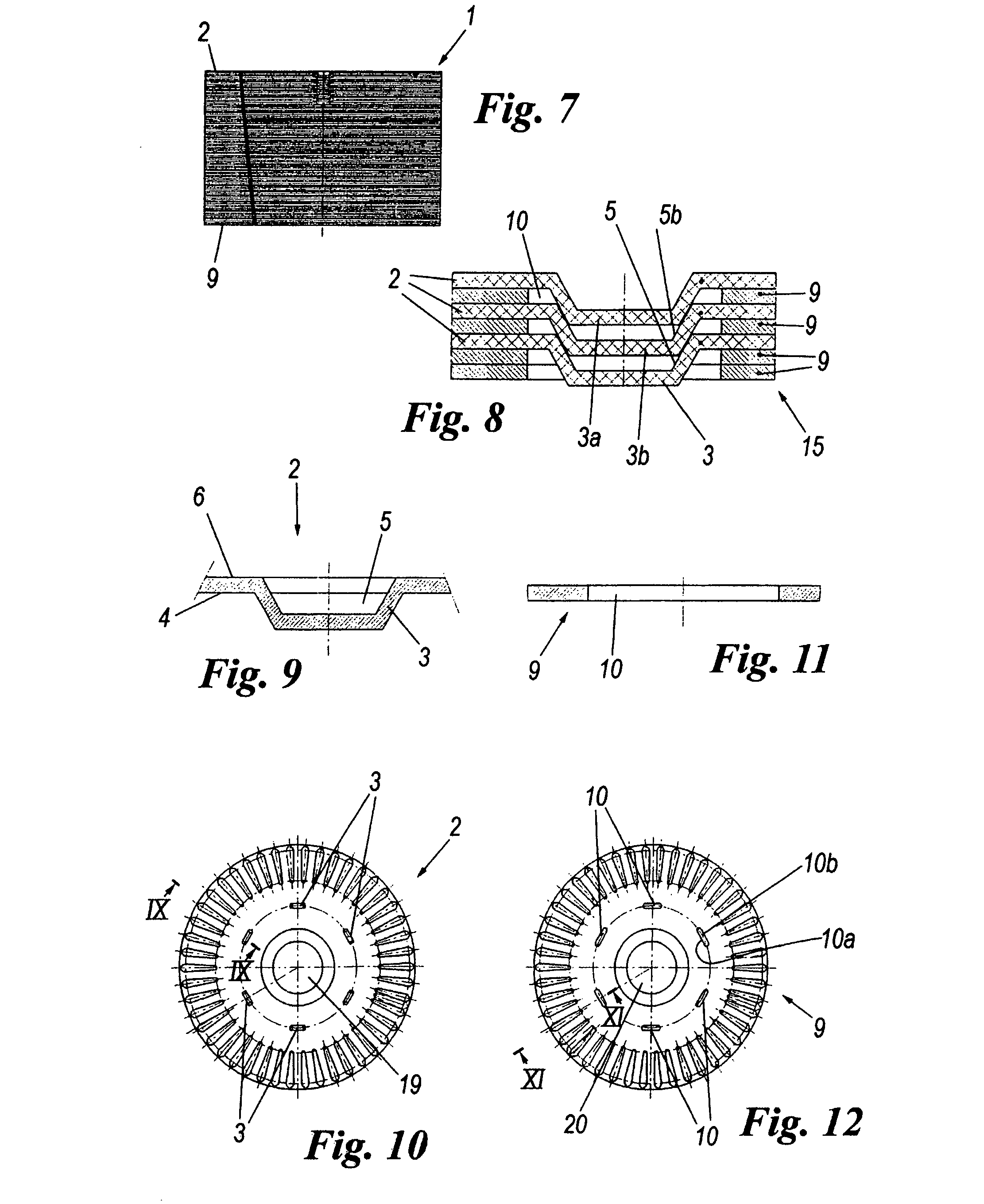
[0049]The rotor of the first embodiment is for example the rotor of an electrical machine such as a motor; it is shown in FIGS. 7-12.

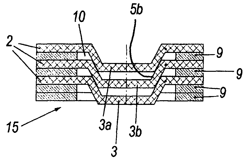
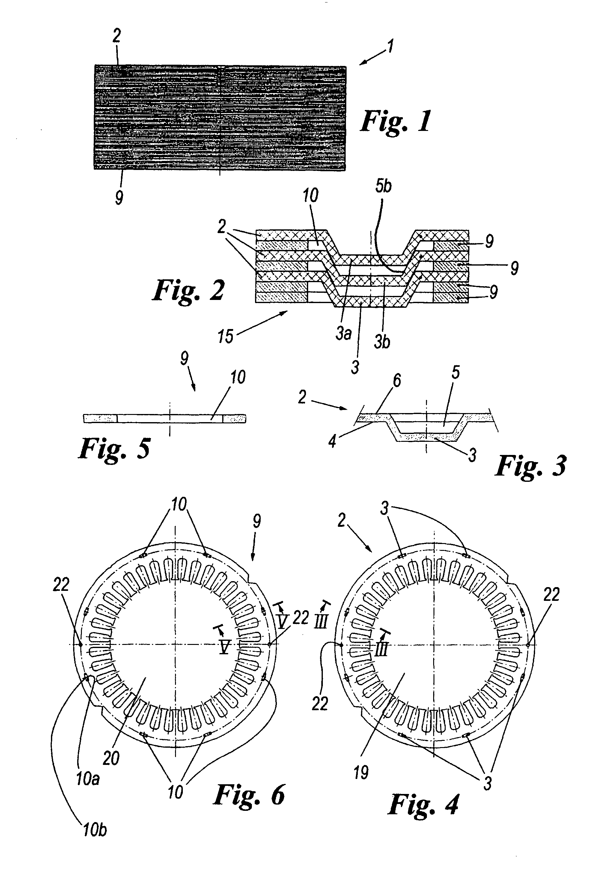
[0050]It comprises a plurality of fixed-together first laminations 2 with interposed second laminations 9.

[0051]Each of the first laminations 2 presents six fasteners 3, the second laminations 9 correspondingly presenting six apertures 10 which are traversed by the fasteners 3 with interference both on the inner-circumference side 10a and on the outer-circumference side 10b of the aperture 10.

[0052]The first end 15 presents two mutually adjacent second laminations 9 retained by the fasteners 3, the opposite end presenting two first laminations 2 directly fixed together by the fasteners 3 and the recesses 5.

[0053]In this case the diameter of the holes 19 in the first laminations 2 and of the holes 20 in the second laminations 9 are equal.

ROTOR

second embodiment

[0054]The rotor of the second embodiment is shown in FIGS. 13-18.

[0055]It has a similar structure to that described in the first embodiment.

[0056]However, in this case the diameter of the holes 19 in the first laminations 2 is greater than the diameter of the holes 20 in the second laminations 9.

[0057]The present invention also relates to a method for producing the described laminar article for electrical use.

[0058]The method consists of die-cutting a plurality of laminations from a metal sheet, rotating the die-cut laminations and superposing them, to then fix them together in predetermined manner.

[0059]The laminations are die-cut with a reference axis thereof rotated through a predetermined angle about a reference axis of the sheet metal, to limit the rotations to be imposed on the laminations during their mutual fixing.

[0060]The invention also relates to a machine for producing the described laminar article for electrical use.

[0061]The machine comprises a plurality of die-cutting...


PUM

PropertyMeasurementUnit
diameteraaaaaaaaaa
angleaaaaaaaaaa
structureaaaaaaaaaa

Abstract

The laminar article for electrical use comprises a plurality of superposed first metal laminations fixed together. Each of the first laminations is provided with at least one fastener projecting from a first surface thereof and defining a recess in its opposite side. Each fastener of one lamination is arranged to fit into a recess of an adjacent lamination. The article presents second laminations interposed between at least two adjacent first laminations fixed together. The second laminations are provided with through apertures which are traversed by the fasteners which fix the adjacent first laminations together. The method consists of die-cutting a plurality of laminations from a metal sheet, rotating the die-cut laminations and superposing them, to then fix them together in predetermined manner. The laminations can be die-cut with a reference axis thereof rotated through a predetermined angle about a reference axis of the sheet metal, to limit the rotations to be imposed on the laminations during their mutual fixing.

Description

FIELD OF THE INVENTION[0001]The present invention relates to a laminar article for electrical use, and to a method and machine for producing said laminar article.BACKGROUND OF THE INVENTION[0002]Electrical machines such as motors or transformers are usually formed from magnetic circuits of lamellar structure, i.e. formed from a plurality of mutually superposed laminations fixed together.DISCUSSION OF THE RELATED ART[0003]Specifically, such laminations are provided with fasteners formed by plastic deformation and projecting from a surface thereof to define a protuberance on one side and a seat on the opposite side; the laminations are traditionally fixed together by inserting the fasteners of one lamination into the seats of a directly adjacent lamination.[0004]However this structure presents numerous drawbacks, including in particular incorrectly coupling adjacent laminations together; in practice, because of the manner in which the fastener / seat pairs are formed, a small air space ...

Claims


Application Information

Patent Timeline
Patent Type & Authority Patents(United States)
IPC IPC(8): H02K1/00
CPCB32B7/08B32B15/00H01F3/02H02K15/02H01F41/0233Y10T29/5137H02K2201/09Y10T29/49117
Inventor BERTOCCHI, GIANLUCAGARDANINI, GIANFRANCOBONETTI, DANIELEPERUCCHI, MAURIZIO
Owner CORRADA SPA
Why Eureka
Try Eureka