Systems, methods, and apparatuses for linear polar transmitters

a linear polar transmitter and transmitter technology, applied in the field of linear polar transmitters, can solve the problems of odd-order in-band distortion terms of low-frequency even-order distortion components, and achieve the effect of greater bandwidth

Inactive Publication Date: 2010-12-28
SAMSUNG ELECTRO MECHANICS CO LTD
View PDF30 Cites 61 Cited by
  • Summary
  • Abstract
  • Description
  • Claims
  • Application Information

AI Technical Summary

Benefits of technology

[0007]Embodiments of the invention may provide for an analog linear polar transmitter using multi-path orthogonal recursive predistortion. This transmitter may operate in a low power mode and achieve greater bandwidth by feeding the low-frequency even-order distortion components (i.e., the deviation from linear gain) back. Moreover, the distortion components may not be added to the input signal as feedback, but rather may be used to predistort the input signal in a multiplicative manner. In particular, the low-frequency even-order distortion components may generate odd-order in-band distortion terms when they are multiplied by the fundamental signal. Thus, such architecture may be inherently more stable than conventional additive polar loop systems.

Problems solved by technology

In particular, the low-frequency even-order distortion components may generate odd-order in-band distortion terms when they are multiplied by the fundamental signal.

Method used


Image

  • Systems, methods, and apparatuses for linear polar transmitters
  • Systems, methods, and apparatuses for linear polar transmitters
  • Systems, methods, and apparatuses for linear polar transmitters

Examples


Embodiment Construction

[0021]The invention now will be described more fully hereinafter with reference to the accompanying drawings, in which some, but not all embodiments of the invention are shown. Indeed, these inventions may be embodied in many different forms and should not be construed as limited to the embodiments set forth herein; rather, these embodiments are provided so that this disclosure will satisfy applicable legal requirements. Like numbers refer to like elements throughout.

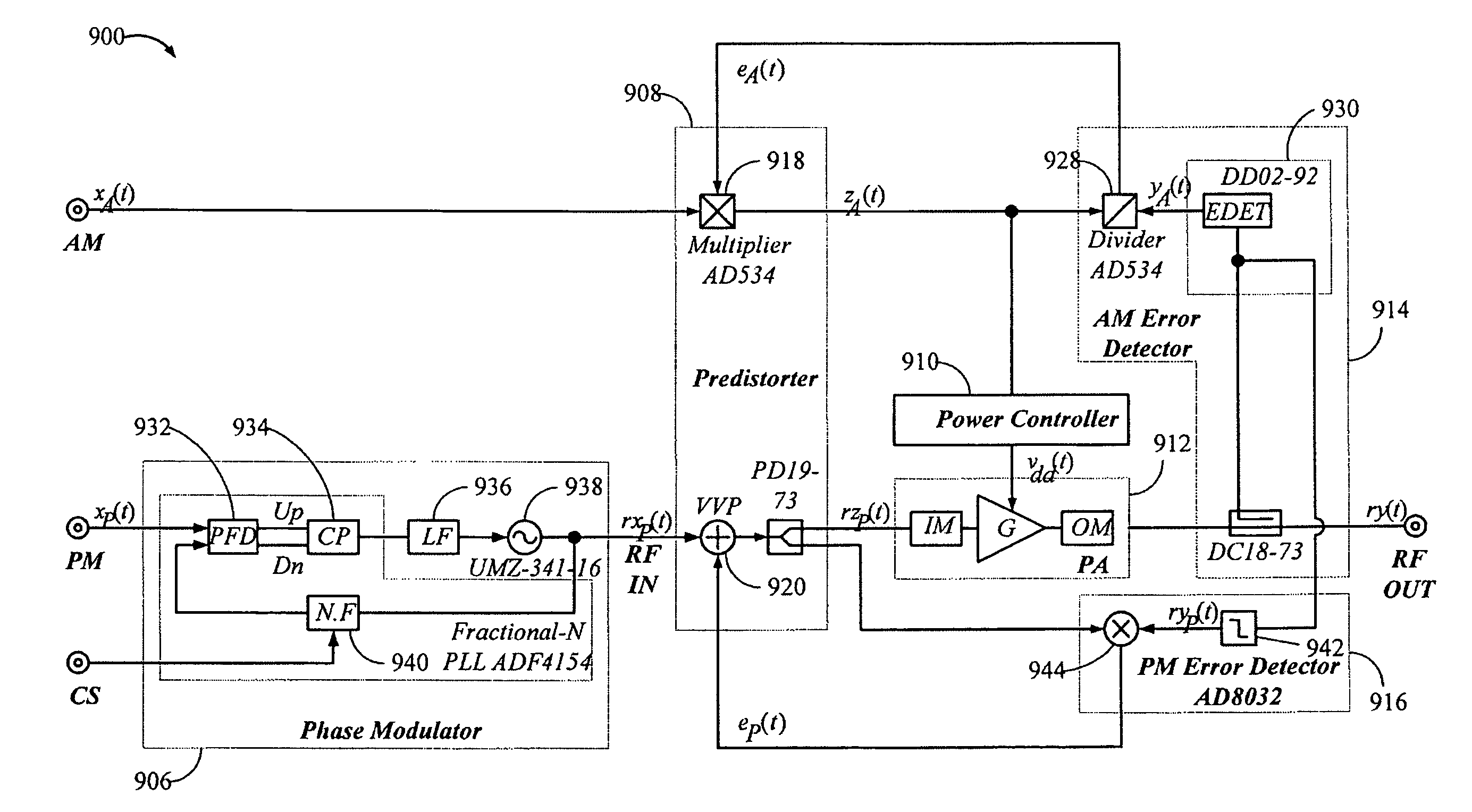
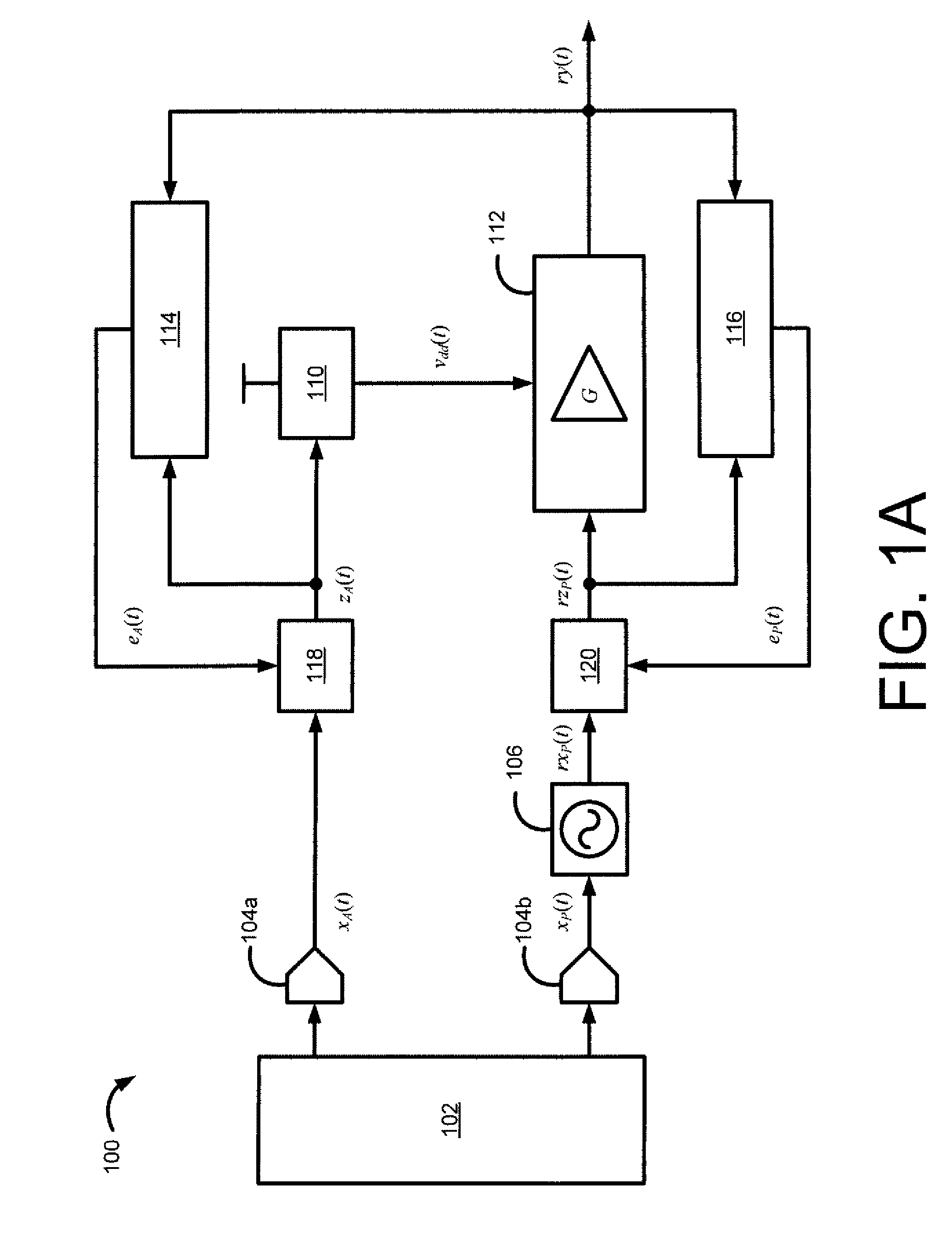
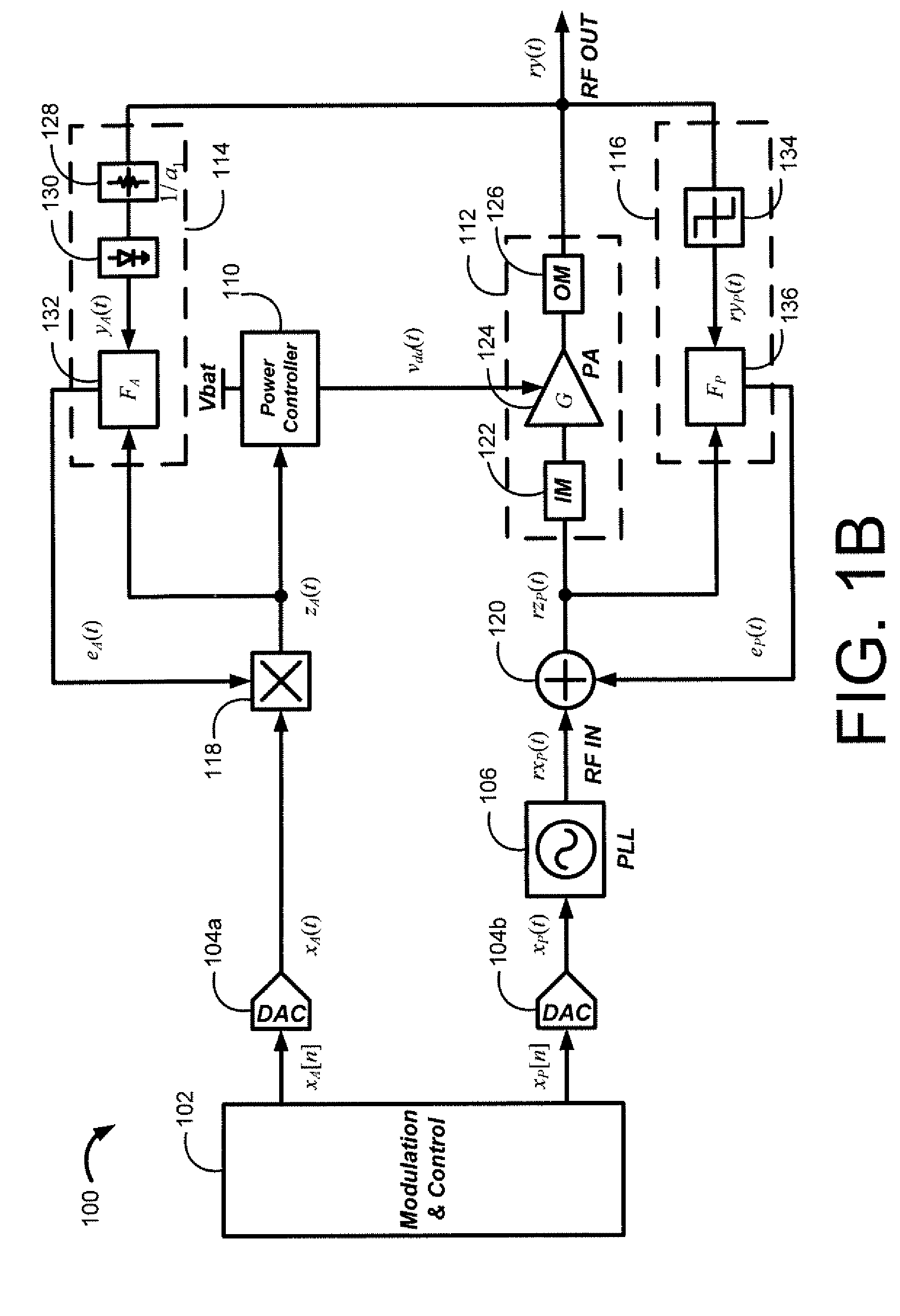
[0022]Embodiments of the invention may provide linear polar transmitters that are based upon a polar modulation technique using two respective paths for amplitude and phase, and an analog orthogonal recursive predistortion linearization technique. The polar modulation technique may enhance the battery life by dynamically adjusting the bias level of a power amplifier. Additionally, the analog orthogonal recursive predistortion may provide for a substantially instantaneous correction of amplitude and phase errors in a rad...


PUM


Abstract

Systems and methods are disclosed for providing a linear polar transmitter. The systems and methods may include generating an input amplitude signal and an input phase signal, where the input amplitude signal and the input phase signal are orthogonal components of an input signal, and where the input amplitude signal and the input phase signal are generated on respective first and second signal paths. The systems and methods may also include processing the input amplitude signal along the first signal path using an amplitude error signal to generate a predistorted amplitude signal, and processing the input phase signal along the second signal path using an phase error signal to generate a predistorted phase signal. The systems and methods may also include providing the predistorted amplitude signal along the first signal path and the predistorted phase signal along the second signal path to a power amplifier to generate an output signal, where the amplitude error signal is generated from a comparison of at least an amplitude portion of the output signal with the predistorted amplitude signal and where the phase error signal is generated from a comparison of at least a phase portion of the output signal with the predistorted phase signal.

Description

RELATED APPLICATION[0001]This application claims priority to U.S. Provisional Ser. No. 60 / 803,871, entitled “Systems, Methods, and Apparatuses for Linear Polar Transmitters,” filed on Jun. 4, 2006, which is incorporated by reference as if fully set forth herein.FIELD OF THE INVENTION[0002]The invention relates generally to linear polar transmitters, and more particularly to systems, methods, and apparatuses for the performance enhancement of radio frequency (RF) power amplifiers.BACKGROUND OF THE INVENTION[0003]In cost-sensitive mobile transmitters, performance trade-offs must be carefully managed to achieve high efficiency and high output power at the required gain and linearity. With an intrinsically nonlinear power amplifier (PA) itself, the only way to achieve a better linear operation is to restrict the dynamic range of signals to a small fraction of the PA's overall capability. Unfortunately, such a restriction in the dynamic range to achieve a more linear operation is quite i...

Claims


Application Information

Patent Timeline
Patent Type & Authority Patents(United States)
IPC IPC(8): H04B1/04
CPCH03F1/0211H03F1/3282H04L27/361H04L27/368H03F2200/324H03F2200/393H03F2200/504H04B1/04
Inventor WOO, WANGMYONGLEE, CHANG-HOCHANG, JAEJOONKIM, HAKSUN
Owner SAMSUNG ELECTRO MECHANICS CO LTD
Why Eureka
Try Eureka