Intravenous pacemaker electrode

a pacemaker electrode and electrode tip technology, applied in the field of intravenous pacemaker electrodes, can solve the problems of difficult to determine whether the electrode tip is there, particularly difficult with known methods, and the ventricle trabecular mesh is a very thin soft tissue, and achieves the effects of reducing the risk of implantation, good resolution, and reducing the computational consideration of the geometry of the pacemaker electrod

Inactive Publication Date: 2010-12-28
SIEMENS HEALTHCARE GMBH
View PDF15 Cites 0 Cited by
  • Summary
  • Abstract
  • Description
  • Claims
  • Application Information

AI Technical Summary

Benefits of technology

[0007]The intravenous pacemaker electrode according to the invention comprises an electrode cable and an electrode head linked thereto, which is provided in order to transmit electrical stimulation pulses. A duct and a line leading to the electrode head run in an electrode cable comprising an insulating sleeve. An ultrasound catheter can be moved into the duct of the electrode cable, said ultrasound catheter comprising a thread-like guide element and an ultrasound measurement element attached to its distal end. The guide element of the ultrasound catheter preferably serves both to advance the ultrasound measurement element in the electrode cable as well as to transmit electrical signals. A measurement element is understood as an ultrasound measurement element, said measurement element comprising both an ultrasound emitter and also an ultrasound receiver. The combination of the pacemaker electrode with the ultrasound measurement element enables an imaging diagnosis with a good resolution in the heart. This diagnosis is particularly advantageous during x-ray illumination carried out simultaneously. The ultrasound catheter is not permanently linked to the remaining parts of the pacemaker electrode, but is however only inserted into the duct of the electrode cable if necessary.
[0008]The duct is preferably closed to such an extent that the ultrasound catheter cannot come into contact with the patient's blood or body tissue. Thus the ultrasound catheter can be used widely, even with different patients. The area of the electrode cable bordering the electrode head is preferably configured such that an ultrasound measurement is possible to a large extent uninfluenced by the material of the pacemaker electrode. For this purpose, an axial distance between the distal end of the duct and the electrode head is advantageous, with the ultrasound catheter, in particular its ultrasound measurement element, being able to be moved through the duct towards the electrode head. At least one window which is transparent for the ultrasound, for instance a window ring, is arranged in the area of the insulating sleeve of the electrode cable bordering the electrode head.
[0009]According to a preferred development, besides the duct for the ultrasound catheter, provision is made for a fluid duct suitable for conveying a contrast means towards the electrode head, and comprising an outlet opening in front of the electrode head. In contrast, provision can also be made for example to guide the contrast means through the same duct which is also suitable for inserting the ultrasound catheter. The use of a contrast means essentially broadens the diagnostic possibilities of the ultrasound examination. The outlet opening of the fluid duct preferably comprises a sealing device, which prevents body fluids from flowing into the electrode cable, in the manner of a non-return valve.
[0010]In addition to the duct for the ultrasound catheter and if necessary to the fluid duct for the contrast means, the electrode cable comprises an advantageous embodiment of a further guide duct provided for the insertion of a guidewire. The guidewire can also be identical to one of the aforementioned ducts. Independent of the total number of ducts in the electrode cable, provision is made according to a preferred development for an exit opening for the ultrasound catheter in the region of the electrode head. This allows the ultrasound measurement element to be moved past the electrode head, provided that the exit opening is located in the electrode head, even out via the electrode head.
[0016]According to a second embodiment the diagnosis and treatment device additionally comprises a telemetry module for intravenous pacemaker electrodes, in particular with the features of the claims, which is arranged in a pacemaker housing to which the electrode cable is connected and also comprises a data link to the ultrasound measurement element. The telemetry module allows the ultrasound measurement data to be read out even after the pacemaker has been implanted. The features of the two previously described exemplary embodiments of a diagnosis and treatment device are particularly advantageously combined. In this case the features of the first embodiment, in other words the computational consideration of the geometry of the pacemaker electrodes can be reduced within the implanted pacemaker or can be realized in an extracorporeal evaluation unit.
[0017]The invention is particularly advantageous in that an imaging diagnosis with good resolution is enabled in the heart by the combination of a pacemaker electrode with an ultrasound catheter which be arranged reversibly therein, whereby the risks involved with implantation are considerably reduced in comparison with an implantation exclusively undertaken using x-ray illumination.

Problems solved by technology

However, trabecular mesh of the ventricle is, in particular, a very thin soft tissue which is only visible, with difficulty, by means of an x-ray device.
It is particularly difficult with known methods to establish whether the electrode tip of the pacemaker electrode is anchored to the tissue in the desired manner.

Method used


Image

  • Intravenous pacemaker electrode
  • Intravenous pacemaker electrode
  • Intravenous pacemaker electrode

Examples


Embodiment Construction

[0025]Parts which correspond to each other or function identically are provided with the same reference characters in all the figures.

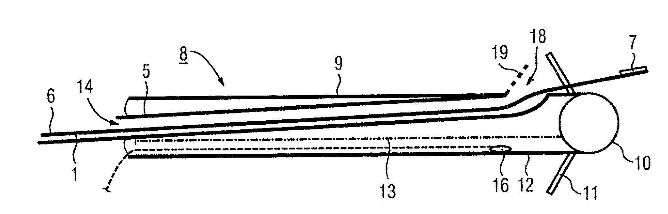
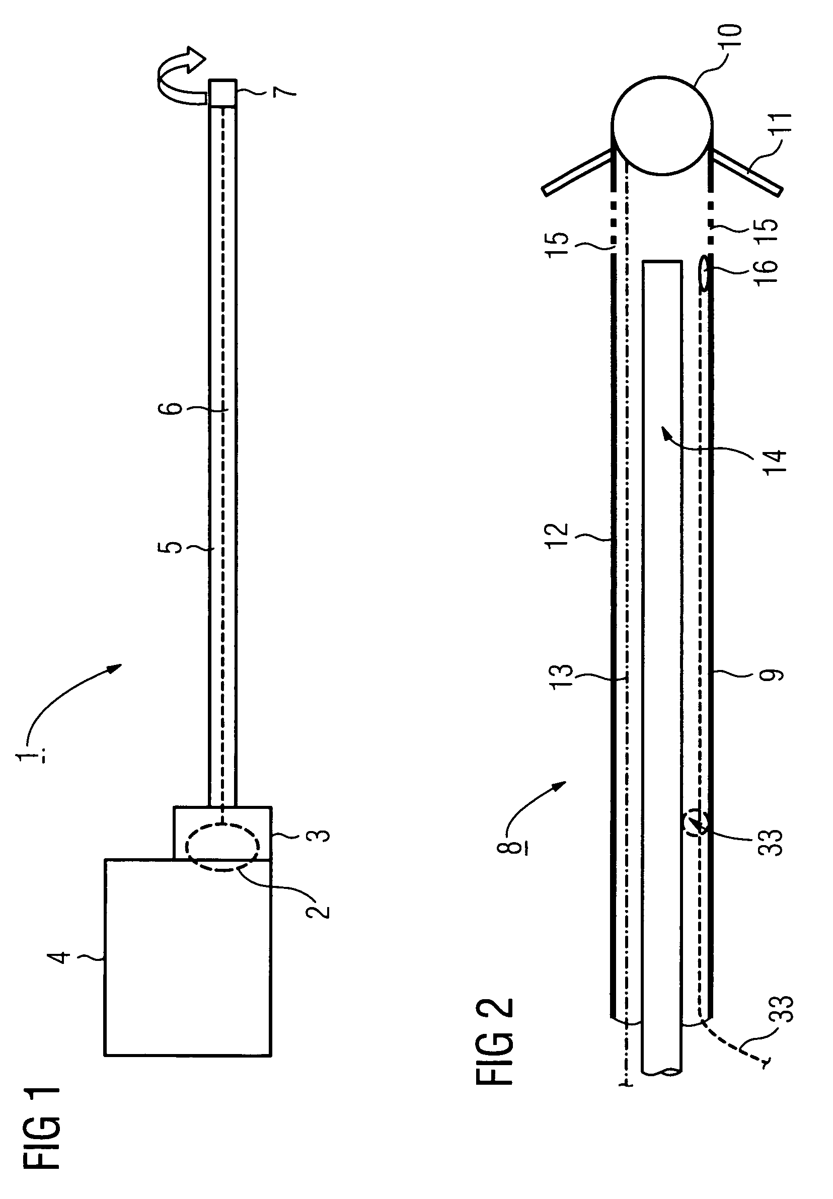
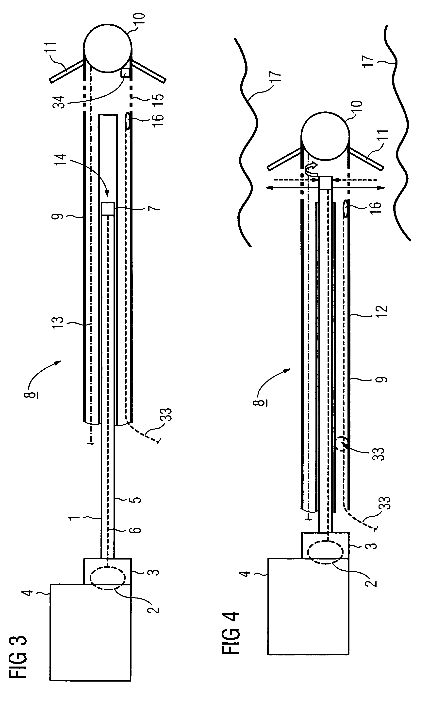
[0026]FIG. 1 shows an ultrasound catheter 1 for use in an intravenous pacemaker electrode (not shown here in further detail). The term pacemaker electrode is to be understood below in a broader sense and also comprises electrodes for ICD's (implantable cardioverters / defibrillators) for instance. An intravascular ultrasound system (IVUS) is known per se from DE 198 27 460 A1 as well as from U.S. Pat. No. 5,193,546 A. The ultrasound catheter 1 can also be used for stimulation electrodes for neurostimulation, which are inserted into the cranium in order to treat a patient with depression or Parkinson's disease for instance.

[0027]The ultrasound catheter 1 according to FIG. 1 is connected to a signal-interface / drive unit 4 for the IVUS examination with the aid of a mechanical linking system 3 comprising a rotation coupling 2. The ultrasound catheter 1 also...


PUM


Abstract

An intravenous pacemaker electrode has an electrode tip designed to release a drug, where the drug contains at least one of the active substances sirolimus, paclitaxel, everolimus, fibrin, rapamycin, and tacrolimus.

Description

CROSS REFERENCE TO RELATED APPLICATION[0001]This application claims priority of the German application No. 10 2004 062 395.3 DE filed Dec. 23, 2004, which is incorporated by reference herein in its entirety.FIELD OF THE INVENTION[0002]The invention relates to an intravenous pacemaker electrode with an electrode cable comprising a conductor, a duct and an insulating sleeve, with an electrode head being attached to the distal end of the line in order to transmit stimulation pulses.BACKGROUND OF THE INVENTION[0003]A pacemaker electrode of this type is known for example from DE 33 00 050 C2.[0004]Pacemaker electrodes serve to transmit stimulation pulses from a pulse generator to the heart, in particular to the atrium and / or to the ventricle. The pacemaker electrodes can be advanced through a vein to the heart with the aid of an insertion instrument, this procedure typically being monitored using x-ray illumination. However, trabecular mesh of the ventricle is, in particular, a very thin...

Claims


Application Information

Patent Timeline
Patent Type & Authority Patents(United States)
IPC IPC(8): A61N1/05
CPCA61N1/056A61B8/12A61B8/4488
Inventor MASCHKE, MICHAEL
Owner SIEMENS HEALTHCARE GMBH
Why Eureka
Try Eureka