

Muzzle flash suppressor
a suppressor and muzzle technology, applied in the field of muzzle devices, can solve the problems of increasing the physical wear and material degradation of the bore in the gun barrel, not completely eliminating flash in all cases, and reducing the effect of the operation of night vision equipment, reducing the effect of light signature intensity, and reducing the impa
- Summary
- Abstract
- Description
- Claims
- Application Information
AI Technical Summary
Benefits of technology
Problems solved by technology
Method used
Image

Examples
Embodiment Construction
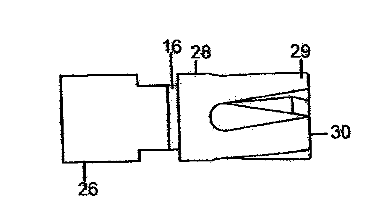
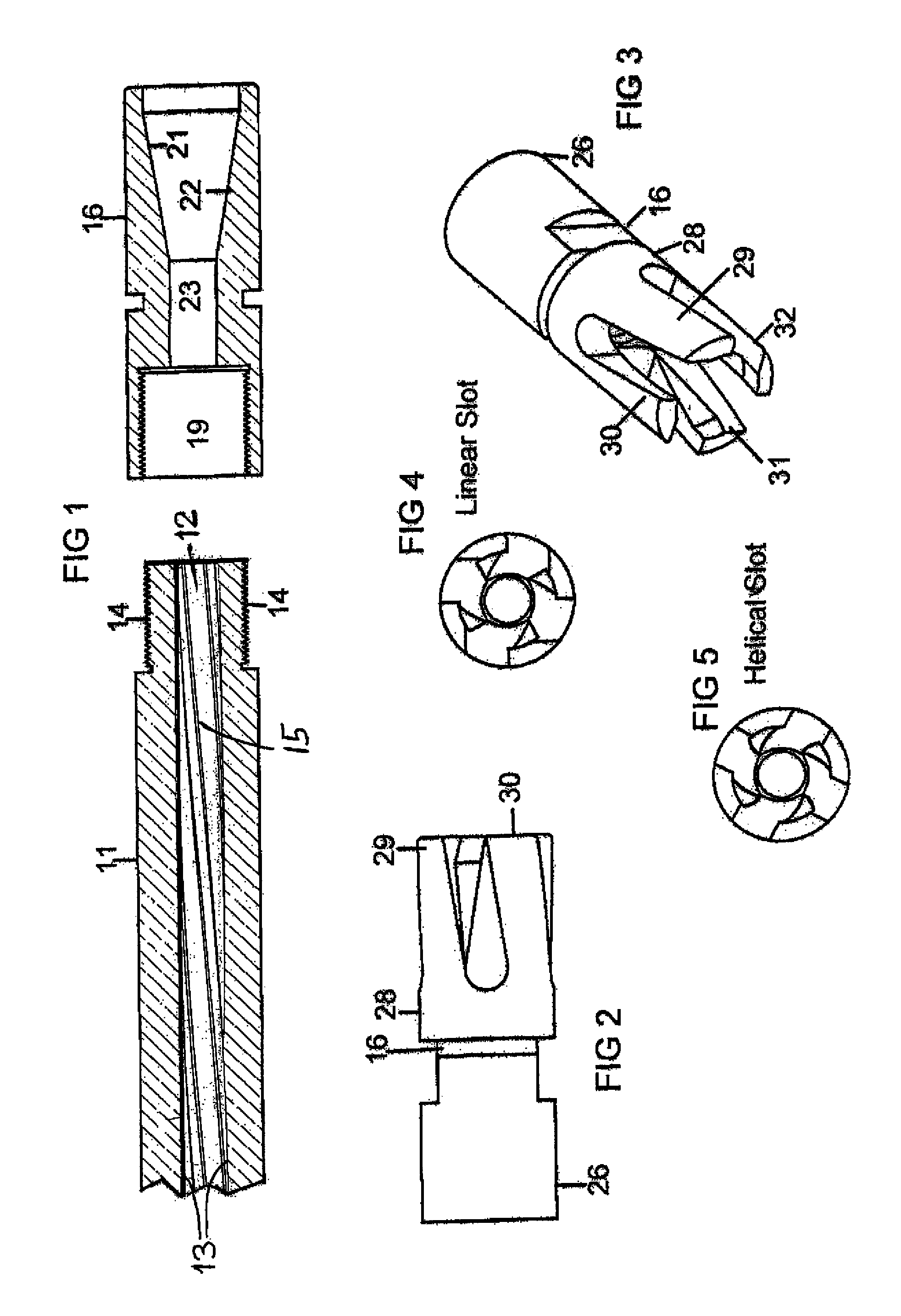
[0020]In FIG. 1, a cross sectional view of the end portion of a weapon barrel 11 is depicted having a central axial bore 12 wherein its cylindrical wall 13 is rifled 15 in accordance with conventional practices for the well known purpose of stabilizing the projectile as it departs from the weapon. The barrel includes a terminal end portion possessing an attachment arrangement including an external threaded portion 14 designed to interface with a flash suppressor 16 through an internal threaded portion 19 for screw on attachment although any convenient attachment arrangement may be used to advantage. Cross sectional areas 21 and 22 illustrate the shape of an internal conical passage way that leads from axial passage 23 and is axially aligned with bore 12 of barrel 11. The shape of cross sectional areas 21 and 22 depict the general configuration of the internal geometry leading from passage way 23 and extending to the terminal end of flash suppressor 16.
[0021]In addition to using fast...
PUM
 Abstract
Description
Claims
Application Information