
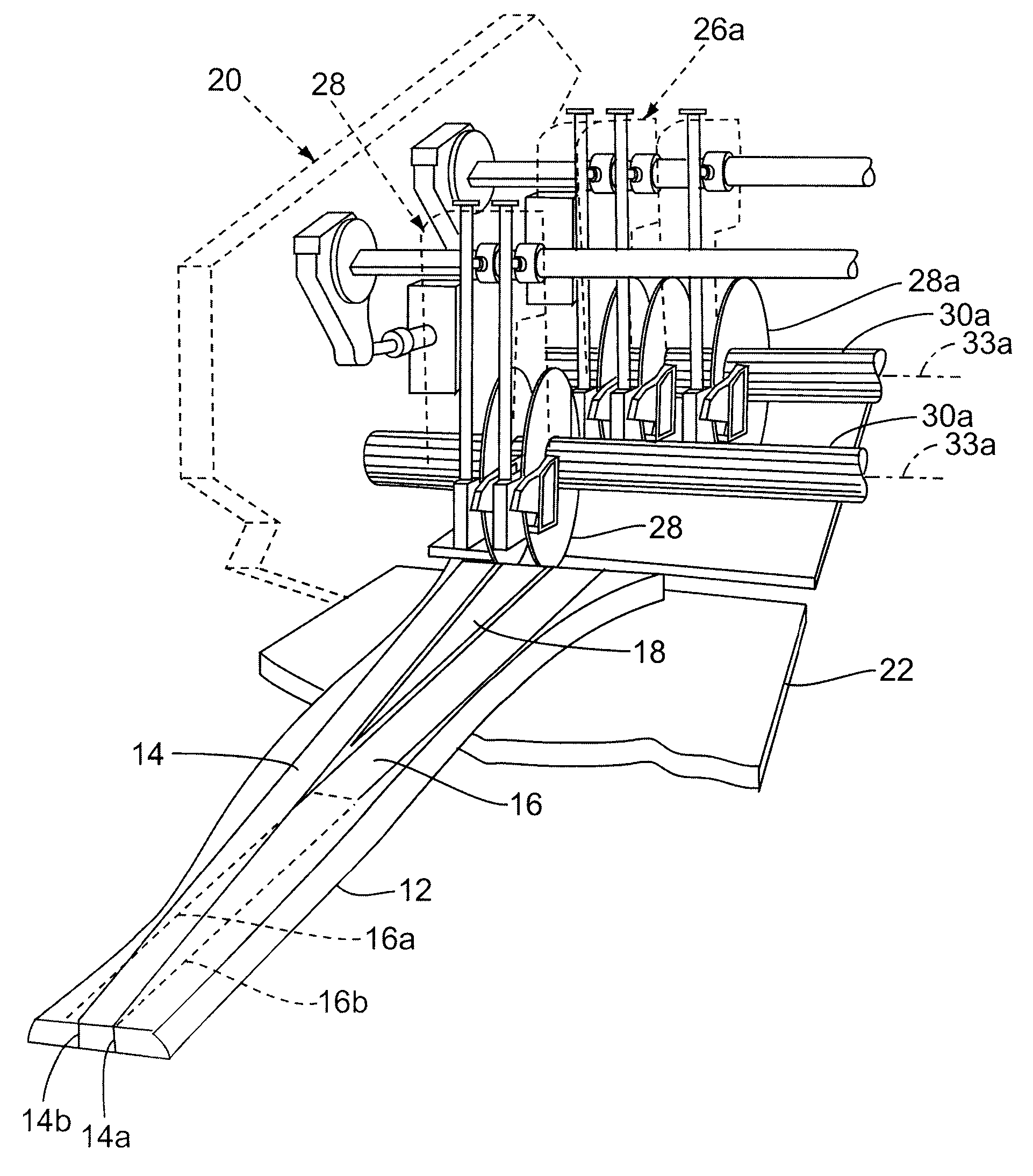
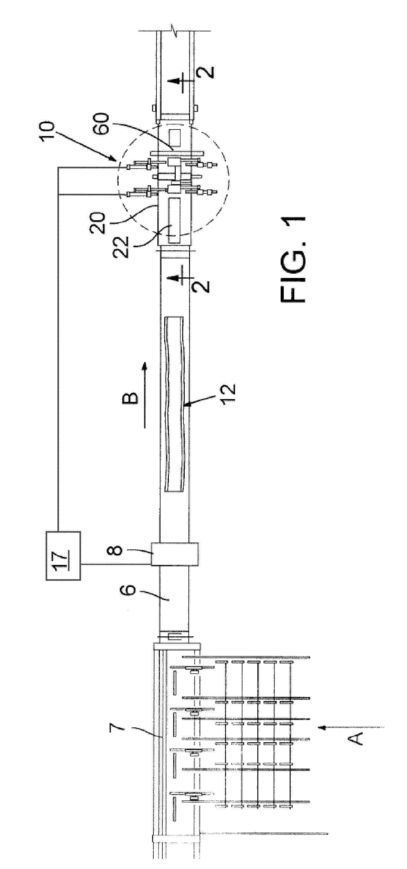
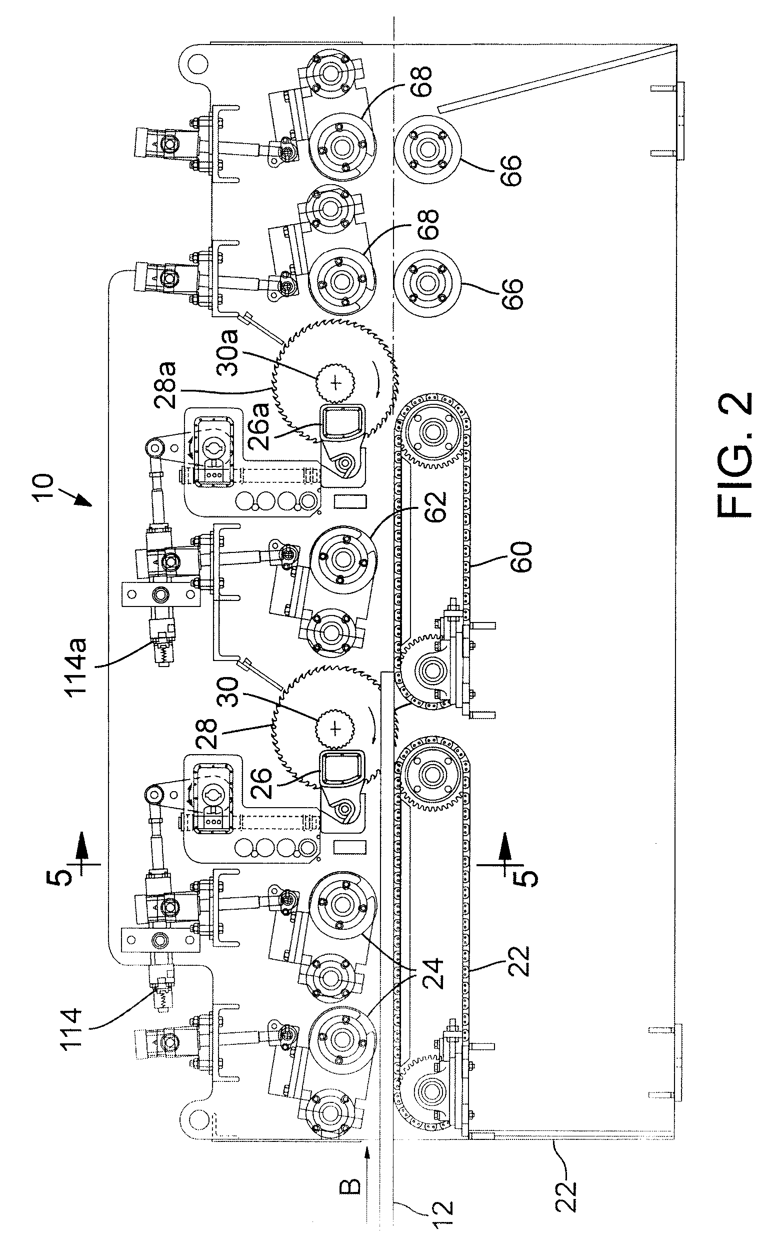
Edger with staggered saws

a technology of active sawguides and edging saws, which is applied in the manufacture of wooden sticks, flat surfacing machines, manufacturing tools, etc., can solve the problems of poor strength characteristics of heartwood and unsuitability for structural grade timber, and the conventional method requires a considerable amount of expensive scanning, positioning and transporting equipment, and achieves the most recovery of structural grade wood

Inactive Publication Date: 2011-01-04
USNRKOCKUMS CANCAR
View PDF12 Cites 8 Cited by
  • Summary
  • Abstract
  • Description
  • Claims
  • Application Information

AI Technical Summary

Benefits of technology

"The present invention is about improving the recovery of higher quality lumber from sap wood by using a trapezoidal sawing solution over a two-board sawing solution. This is particularly useful for species that can be affected by heart rot or high taper. The invention provides an active sawguide and arbor assembly with staggered arbors and sawguides that can independently follow a different optimized path to recover the best quality wood from the workpiece. The sawguides are actively positioned and skewed by corresponding actuators to optimize the cutting solution. The method also involves actively skewing and slewing the saws to cut the boards from the workpiece. Overall, the invention enhances the recovery of structural grade wood and improves the value of the sawing process."

Problems solved by technology

One of the problems with these trees and other species is that the heartwood has poor strength characteristics and is unsuitable for structural grade timber.
Previous edge trimmers, typically known as edgers, have not adequately addressed this difficulty.
This conventional method requires a considerable amount of expensive scanning, positioning and transporting equipment to carry out the process.
Conventional systems also commonly create cumulative scanning, positioning and transport errors that make the systems somewhat less than optimal.
In addition, many conventional curve edging systems are limited in terms of the width of boards that may be cut from a flitch.
However, it will be appreciated that these board widths may not correspond to the maximum widths available to be cut form a flitch based upon the usable sapwood of the flitch.

Method used


Image

  • Edger with staggered saws
  • Edger with staggered saws
  • Edger with staggered saws

Examples


Embodiment Construction

In the following detailed description, reference is made to the accompanying drawings which form a part hereof, and in which are shown by way of illustration embodiments in which the invention may be practiced. It is to be understood that other embodiments may be utilized and structural or logical changes may be made without departing from the scope of the present invention. Therefore, the following detailed description is not to be taken in a limiting sense, and the scope of embodiments in accordance with the present invention is defined by the appended claims and their equivalents.

Various operations may be described as multiple discrete operations in turn, in a manner that may be helpful in understanding embodiments of the present invention; however, the order of description should not be construed to imply that these operations are order dependent.

The description may use perspective-based descriptions such as up / down, back / front, and top / bottom. Such descriptions are merely used ...


PUM

PropertyMeasurementUnit
skewing angleaaaaaaaaaa
skew angleaaaaaaaaaa

Abstract

Embodiments of the present invention provide a wood processing machine adapted to cut wood workpieces along multiple optimized cutting paths. In various embodiments, the wood processing machine includes a first saw assembly and a second saw assembly that is disposed down stream from the first saw assembly. The first saw assembly is adapted to cut the workpiece along the first optimized cutting path and the second saw assembly is adapted to cut the workpiece along the second optimized cutting path.

Description

TECHNICAL FIELDEmbodiments of the present invention relate to a method and an apparatus for edging workpieces such as flitches, and, more specifically, to a pair of staggered active sawguide packages which are constantly adjusted to corresponding target lines during sawing, for edging workpieces according to an optimized profile.BACKGROUNDIncreasingly, many parts of the world are growing plantation forest of Radiata Pine, Eucalyptus and other fast growing species. One of the problems with these trees and other species is that the heartwood has poor strength characteristics and is unsuitable for structural grade timber. Consequently, it is used for non-structural purposes such as pallet stock where its value is roughly one third that of structural lumber. Structural lumber is made from the outside, or sapwood of the tree. Accordingly, any structural lumber cut from flitches of these varieties, or having other heartwood deficiencies, is required to be cut by avoiding the heartwood whi...

Claims


Application Information

Patent Timeline
Patent Type & Authority Patents(United States)
IPC IPC(8): B23Q15/00B26D5/00
CPCB27B7/04Y10T83/155Y10T83/173Y10T83/6588Y10T83/659Y10T83/7876
Inventor MITCHELL, RORY M.
Owner USNRKOCKUMS CANCAR
Learn More