Device mounted apparatus, test head, and electronic device test system

a test head and electronic device technology, applied in individual semiconductor device testing, semiconductor/solid-state device testing/measurement, instruments, etc., can solve the problems of difficulty in securing high-precision test of ic chips under test, low s/n ratio of high frequency circuits, and high temperature of pin electronics cards. achieve the effect of suppressing noise propagation and high-precision tes

Inactive Publication Date: 2011-01-04
ADVANTEST CORP
View PDF12 Cites 2 Cited by
  • Summary
  • Abstract
  • Description
  • Claims
  • Application Information

AI Technical Summary

Benefits of technology

[0009]The present invention has as its object the provision of a device mounted apparatus able to suppress propagation of noise between devices mounted on a board and secure a high precision test of the device under test and a test head and electronic device test system.
[0011]In the present invention, the device cooling cover is divided into a first cover and a second cover. These are electrically insulated from each other. Part of the devices among the plurality of devices mounted on the board are covered by the first cover, while at least other part of the devices are covered by the second cover. Due to this, for example, by covering devices easily generating electromagnetic waves etc. by the first cover and covering devices susceptible to noise by the second cover, it is possible to prevent the propagation of noise from one device to another device and possible to secure high precision testing.
[0014]Due to this, for example it is possible to reduce the number of bolts or other fastening means and make efficient use of the space on the board.
[0017]The first cover and the second cover are communicated through holes formed in the part where the first cover and the second cover face each other across the board. Due to this, it is possible to simplify the connection structure of the channel between the first cover and the second cover.

Problems solved by technology

The various devices of a pin electronics card become high in temperature due to the heat they generate at the time of testing IC chips under test.
Therefore, the current generated in the cover due to the electromagnetic waves etc. radiated from the power circuits is propagated as noise to the high frequency circuits, a drop in the S / N ratios of the high frequency circuits etc. is caused and a securing of high precision tests of IC chips under test becomes difficult in some cases.
Further, depending on the timing of generation of the noise source or frequency component, sometimes the test quality will fluctuate for the IC chips under test.
As a result, it sometimes becomes difficult to secure high precision tests.

Method used


Image

  • Device mounted apparatus, test head, and electronic device test system
  • Device mounted apparatus, test head, and electronic device test system
  • Device mounted apparatus, test head, and electronic device test system

Examples


Embodiment Construction

[0061]Below, embodiments of the present invention will be explained based on the drawings.

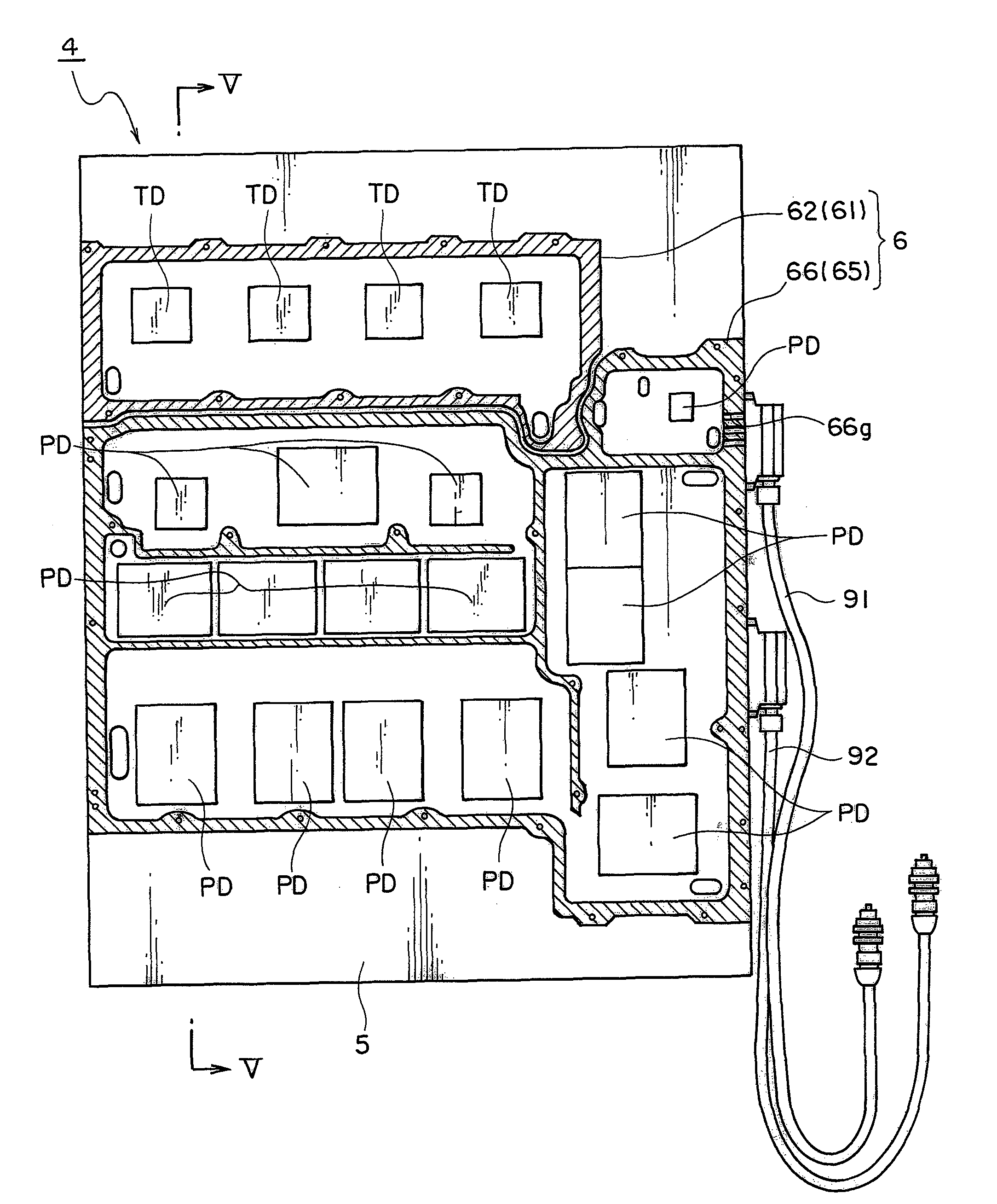
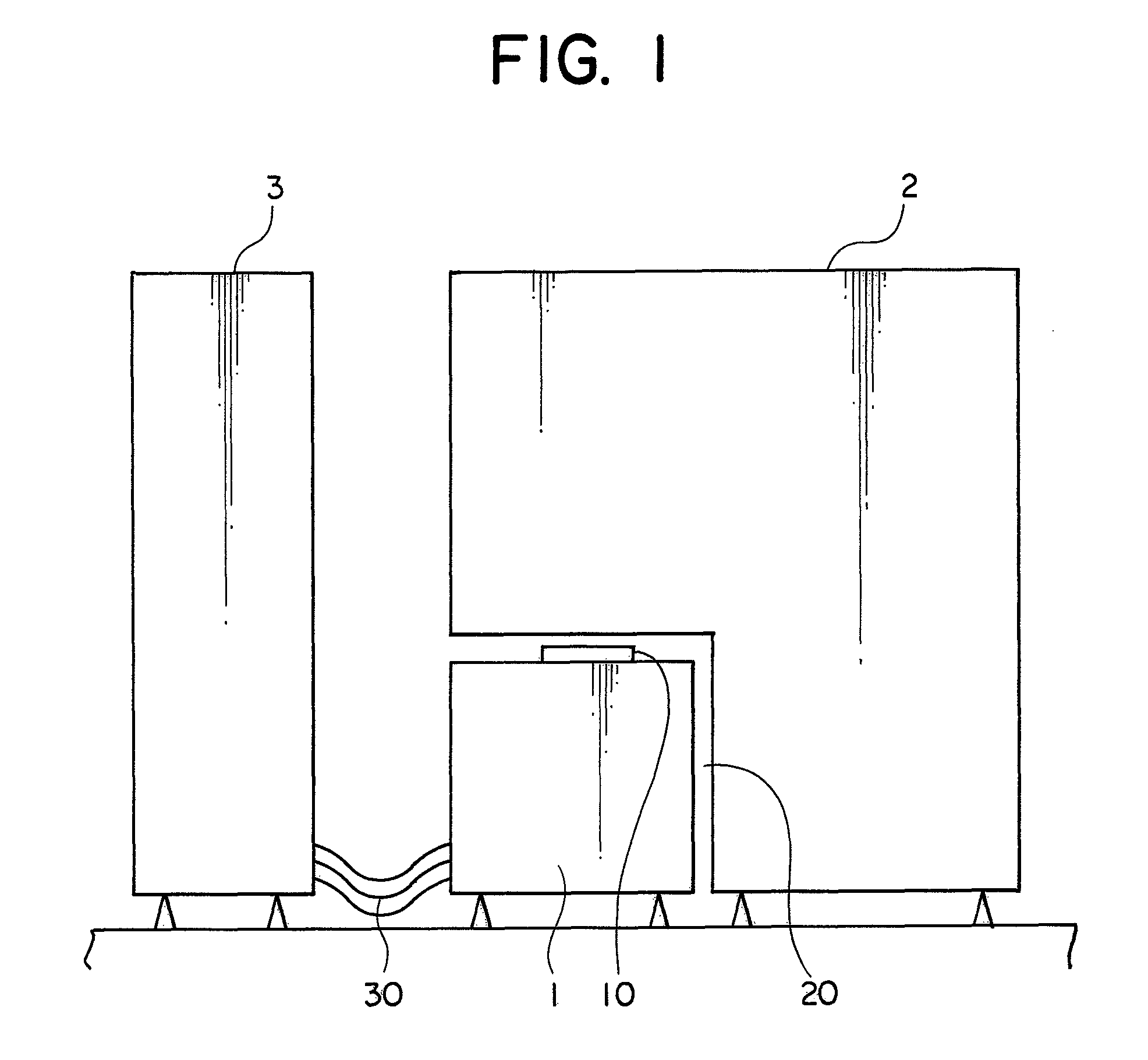
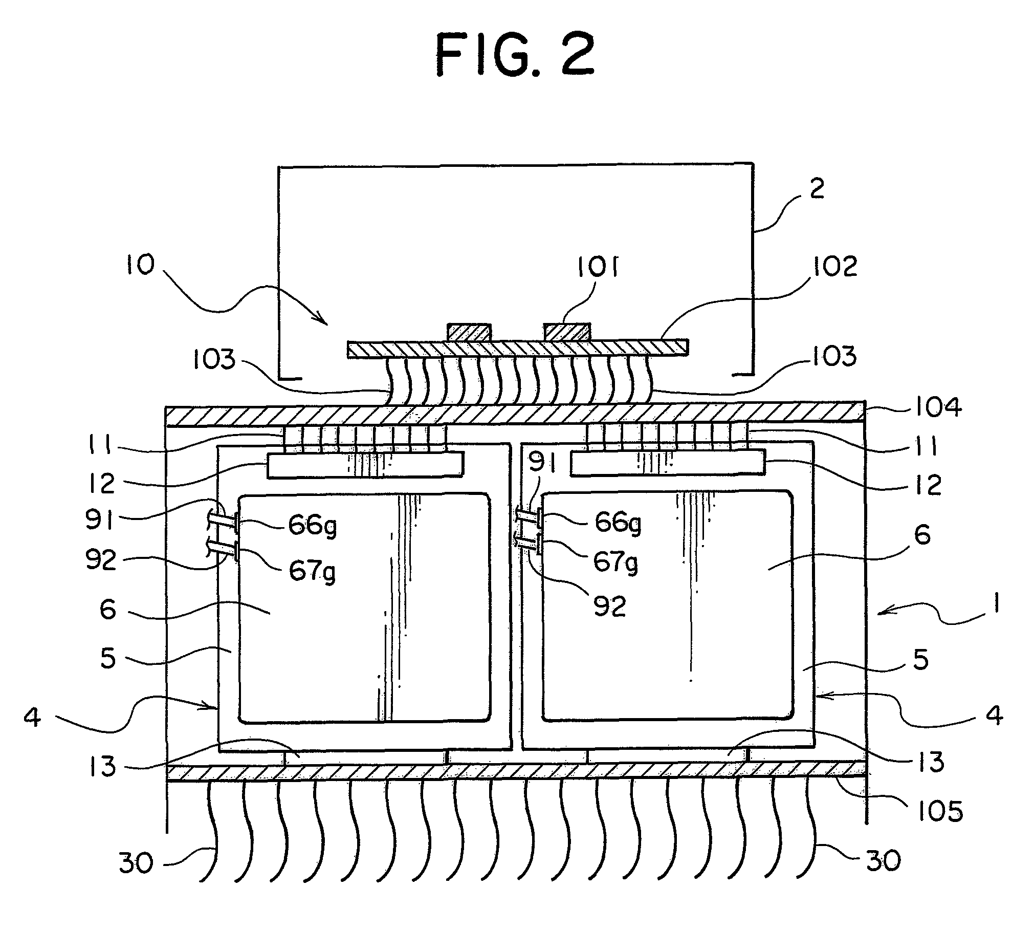
[0062]FIG. 1 is a side view showing an overall electronic device test system according to an embodiment of the present invention, FIG. 2 is a schematic front cross-sectional view showing a test head according to an embodiment of the present invention, and FIG. 3 is a schematic side cross-sectional view showing a test head according to an embodiment of the present invention.

[0063]As shown in FIG. 1, the test head 1 according to the embodiment of the present invention is arranged exchangeably in a space part 20 provided at the bottom part of the handler 2 and is electrically connected through a cable 30 to the tester 3.

[0064]As shown in FIG. 2 and FIG. 3, a contact part 10 is provided at the top part of the test head 1. An IC chip under test is tested by being brought into electrical contact with a socket 101 of the contact part 10 through holes formed in the handler 2.

[0065]The handler 2 success...


PUM


Abstract

A device mounted apparatus includes a board on which a plurality of devices are mounted and a device cooling cover covering the plurality of devices, and formed inside it with a channel through which a refrigerant can flow. The device cooling cover includes a first cover covering only the measurement device among the plurality of devices, and a second cover covering only the power device among the plurality of devices. The first cover and the second cover are electrically insulated from each other.

Description

TECHNICAL FIELD[0001]The present invention relates to a device mounted apparatus comprising: a board on which a device is mounted; and a device cooling cover for cooling the device mounted on the board, and a test head and electronic device test system comprising that device mounted apparatus.BACKGROUND ART[0002]In the process of production of semiconductor devices, an electronic device test system is necessary for testing the finally produced IC chips or other electronic devices. This type test of electronic device is executed by inputting a test pattern to the IC chip under test, operating it and inspecting the response pattern in the state with the test environment set a temperature environment of an ordinary temperature, high temperature, or low temperature.[0003]A general electronic device test system comprises: a tester storing a program for sending out a test pattern and inspecting a response pattern; a test head having contact terminals for electrically connecting this teste...

Claims


Application Information

Patent Timeline
Patent Type & Authority Patents(United States)
IPC IPC(8): G01R31/00
CPCG01R31/2877G01R31/26H01L22/00
Inventor NISHIURA, KOEI
Owner ADVANTEST CORP
Why Eureka
Try Eureka