Flangeless insulation product for compression fitting into insulation cavities

a technology of compression fitting and insulation cavity, which is applied in the direction of heat-proofing, transportation and packaging, walls, etc., can solve the problems of inability to perform at the designed efficiency, inconvenient installation, and increased installation cost of both types of products, so as to improve the sealing effect of the facing material. , the effect of increasing the width of the facing material

Active Publication Date: 2011-01-11
OWENS CORNING INTELLECTUAL CAPITAL LLC
View PDF15 Cites 18 Cited by
  • Summary
  • Abstract
  • Description
  • Claims
  • Application Information

AI Technical Summary

Benefits of technology

The above objects as well as other objects not specifically enumerated are achieved by a system for providing insulation products for a plurality of insulation wall cavities in buildings, where a substantial portion of the insulation wall cavities have a known nominal width. The system includes providing flangeless insulation products having a blanket of fibrous insulation material and having a facing material with a width substantially equal to the width of the insulation blanket, with the width of the insulation blanket and the width of the facing material being greater than the nominal width of the plurality of insulation cavities. The increased width of the facing material improves the seal of the facing material when the insulation product is placed within insulation wall cavities of the known nominal width in comparison to the seal provided by flanged insulation products applied with inset stapling to the same insulation wall cavities.
According to this invention there is also provided a system for providing insulation products for a plurality of insulation wall cavities in buildings, where a substantial portion of the insulation wall cavities have a known nominal width, the system comprising providing flangeless insulation products having a blanket of fibrous insulation material and a facing material, with the facing material having a width wider than the width of the insulation blanket by an amount within the range of from about 1.0 percent to about 3.0 percent of the width of the insulation blanket, with the width of the facing material being greater than the nominal width of the plurality of insulation cavities, wherein the increased width of the facing material improves the seal of the facing material when the insulation products are placed within insulation wall cavities of the known nominal width in comparison to the seal provided by flanged insulation products applied with inset stapling to the same insulation wall cavities.

Problems solved by technology

This would result in a damp insulation product, which is incapable of performing at its designed efficiency.
Installation associated with both types of products is often time consuming, labor intensive, and subsequently expensive, due to the necessity of containing the insulation product using additional layers of material and / or fastening means.
Installation of stapled flanges often results in gaps between staples securing the facing, and this can lead to air leaks and moisture absorption into the insulation product.
These gaps between the fastening means or the placement of an additional vapor barrier material can also result in an unattractive appearance of the installed product as well.
Binderless products are significantly less rigid than hindered insulation products, thus making the binderless product more difficult to install.
However, binderless products lack the stiffness of bindered products, subsequently making the binderless products hard to handle.
Additionally, the fibers in binderless products can become unevenly distributed, and such uneven distribution has a negative impact on the performance of the insulation product.

Method used


Image

  • Flangeless insulation product for compression fitting into insulation cavities
  • Flangeless insulation product for compression fitting into insulation cavities
  • Flangeless insulation product for compression fitting into insulation cavities

Examples


Embodiment Construction

While the description and drawings disclose insulation products of fiberglass insulation, it is to be understood that the insulation material can be any compressible fibrous insulation material, such as rock wool and such as polypropylene.

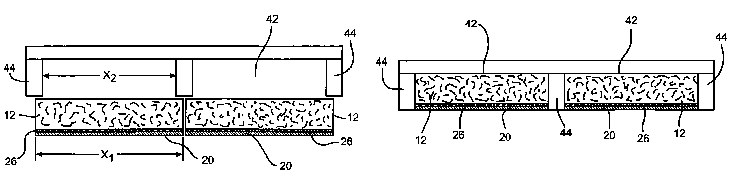
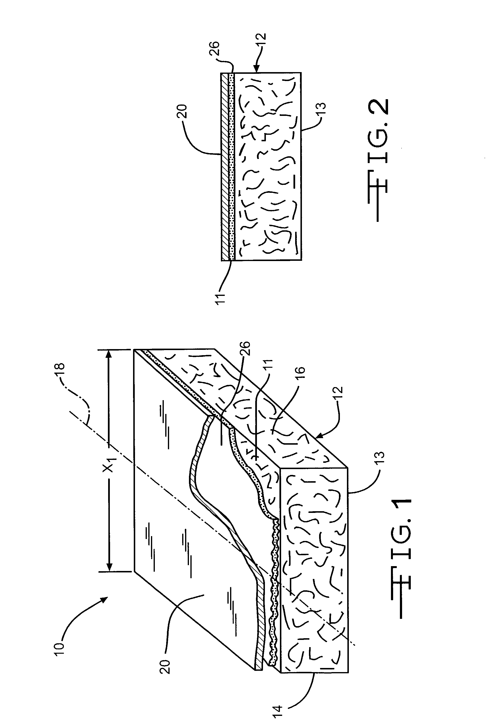
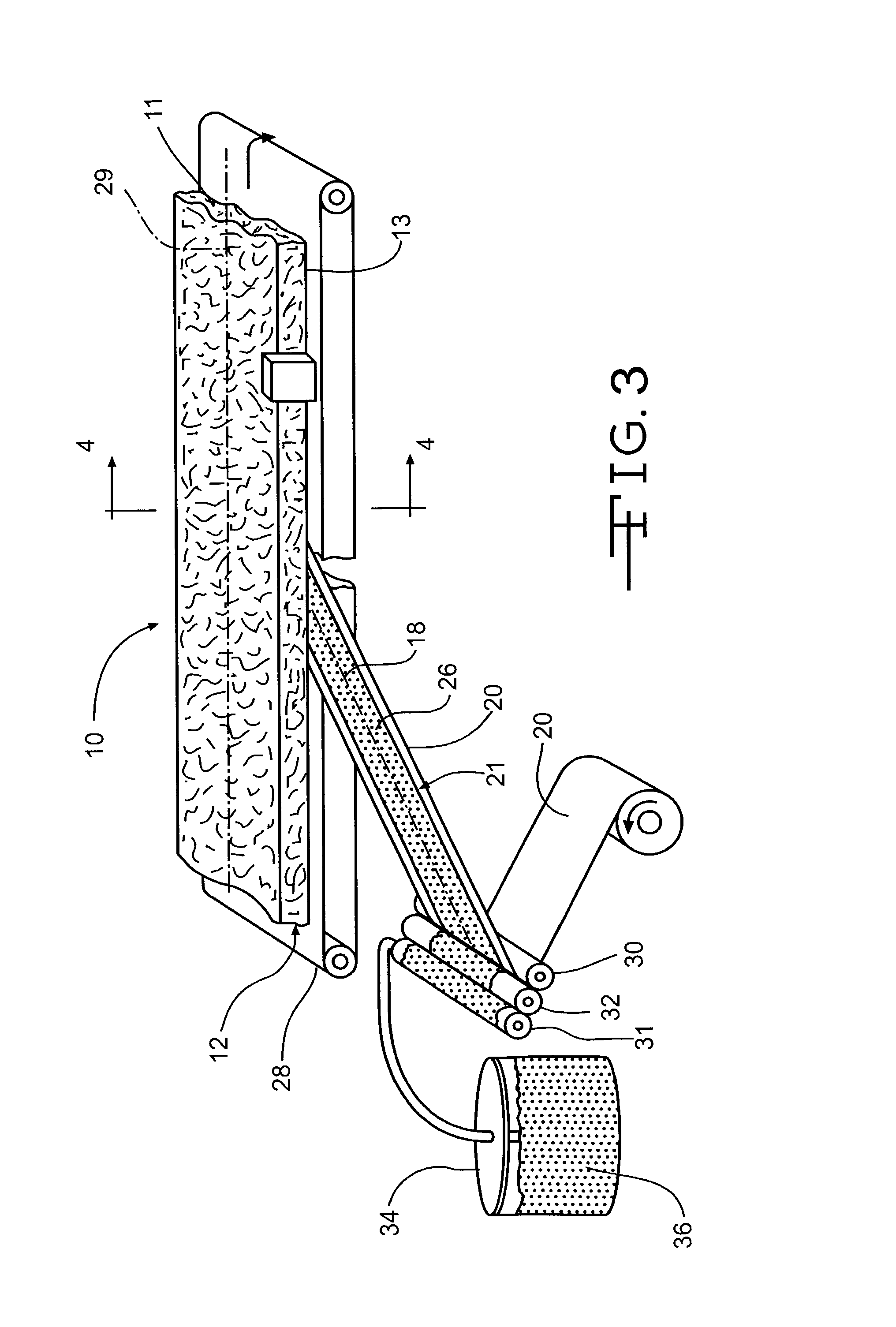
As shown in FIGS. 1 and 2, the insulation product of the invention, indicated generally at 10, is comprised of an elongated strip of fibrous insulation blanket 12, and a facing 20 adhered to a major surface defined by edges 14 and 16 of the fibrous insulation blanket 12. The fibrous insulation blanket 12 is preferably fibrous glass having a density within the range of from about 0.3 to about 1.5 pounds per cubic foot (pcf), although other densities can be used. Also, other fibers, such as mineral fibers of rock, slag or basalt, can be used as well as organic fibers, such as the polymer fibers polypropylene, polyester and polysulfide. The fibers are preferably, but not necessarily, bonded together with a binder material, such as a urea phenol-formal...


PUM

PropertyMeasurementUnit
widthaaaaaaaaaa
densityaaaaaaaaaa
densityaaaaaaaaaa

Abstract

A system provides insulation products for a plurality of insulation wall cavities in buildings, where a substantial portion of the insulation wall cavities have a known nominal width. The system includes providing flangeless insulation products having a blanket of fibrous insulation material and having a facing material with a width substantially equal to the width of the insulation blanket, with the width of the insulation blanket and the width of the facing material being greater than the nominal width of the plurality of insulation cavities. The increased width of the facing material to improves the seal of the facing material when the insulation product is placed within insulation wall cavities of the known nominal width in comparison to the seal provided by flanged insulation products applied with inset stapling to the same insulation wall cavities.

Description

TECHNICAL FIELDThis invention relates to a fibrous insulation product. In particular, this invention pertains to a flangeless fibrous insulation product that is designed for compression fitting into wall cavities of a known nominal width in buildings.BACKGROUND OF THE INVENTIONFibrous insulation is typically formed by fiberizing molten material and depositing the fibers on a collecting conveyor. Typically the fibers for insulation products are mineral fibers, such as glass fibers, although some insulation products are made of organic fibers, such as polypropylene and polyester. Most fibrous insulation products contain a binder material to bond the fibers together where they contact each other, forming a lattice or network. The binder gives the insulation product resiliency for recovery after packaging, and provides stiffness and handleability so that the product can be handled and applied as needed in the wall cavities of buildings. During manufacturing the insulation is cut into wi...

Claims


Application Information

Patent Timeline
Patent Type & Authority Patents(United States)
IPC IPC(8): E04B1/62E04B1/74B32B5/02E04B1/76
CPCB32B5/02E04B1/7604E04B1/7662Y10T428/2476Y10T428/24942B32B2307/7246B32B11/06B32B11/10B32B2317/122B32B2307/206B32B2262/101B32B7/12B32B3/26
Inventor BABBITT, WILLIAM M.PRICE, WILLIARD W.
Owner OWENS CORNING INTELLECTUAL CAPITAL LLC
Why Eureka
Try Eureka