
Power plant

a power plant and power technology, applied in the direction of non-mechanical valves, fluid couplings, valve drives, etc., can solve the problems of pollution and greenhouse effect, global economy impacted by the high price of oil fuel,

Active Publication Date: 2011-01-11
NIEN YU HUN
View PDF6 Cites 9 Cited by
  • Summary
  • Abstract
  • Description
  • Claims
  • Application Information

AI Technical Summary

Benefits of technology

[0005]The present invention is providing a power plant, which produces power by using high pressure gas to push a piston. The power plant does not exhaust pollution and produce greenhouse effect.
[0007]Compared with the conventional power plants, the present power plant uses the high pressure gas to press the piston and drive the crank member. Therefore, the present power plant has a simple structure better than the conventional power plants using the oil fuel. Furthermore, the gas can be easily obtained and cheap, and has no pollution and no greenhouse effect. The present power plant operates without burning the oil fuel, and operates safely and quietly, and is worth to be used widely.

Problems solved by technology

Now, problems of energy sources focus on pollution produced by burning oil fuel, greenhouse effect, and exhausting in the future 30-50 years, etc.
Therefore, the oil fuel of the gas engines or engines burned will produce the pollution and produce the greenhouse effect.
Furthermore, since the oil fuel is an unregenerate energy source, with the price of the oil fuel raises increasingly, global economy is impacted increasingly by the high price of the oil fuel.

Method used


Image

  • Power plant
  • Power plant
  • Power plant

Examples


Embodiment Construction

[0016]Reference will now be made to the drawings to describe a preferred embodiment of the present power plant, in detail.

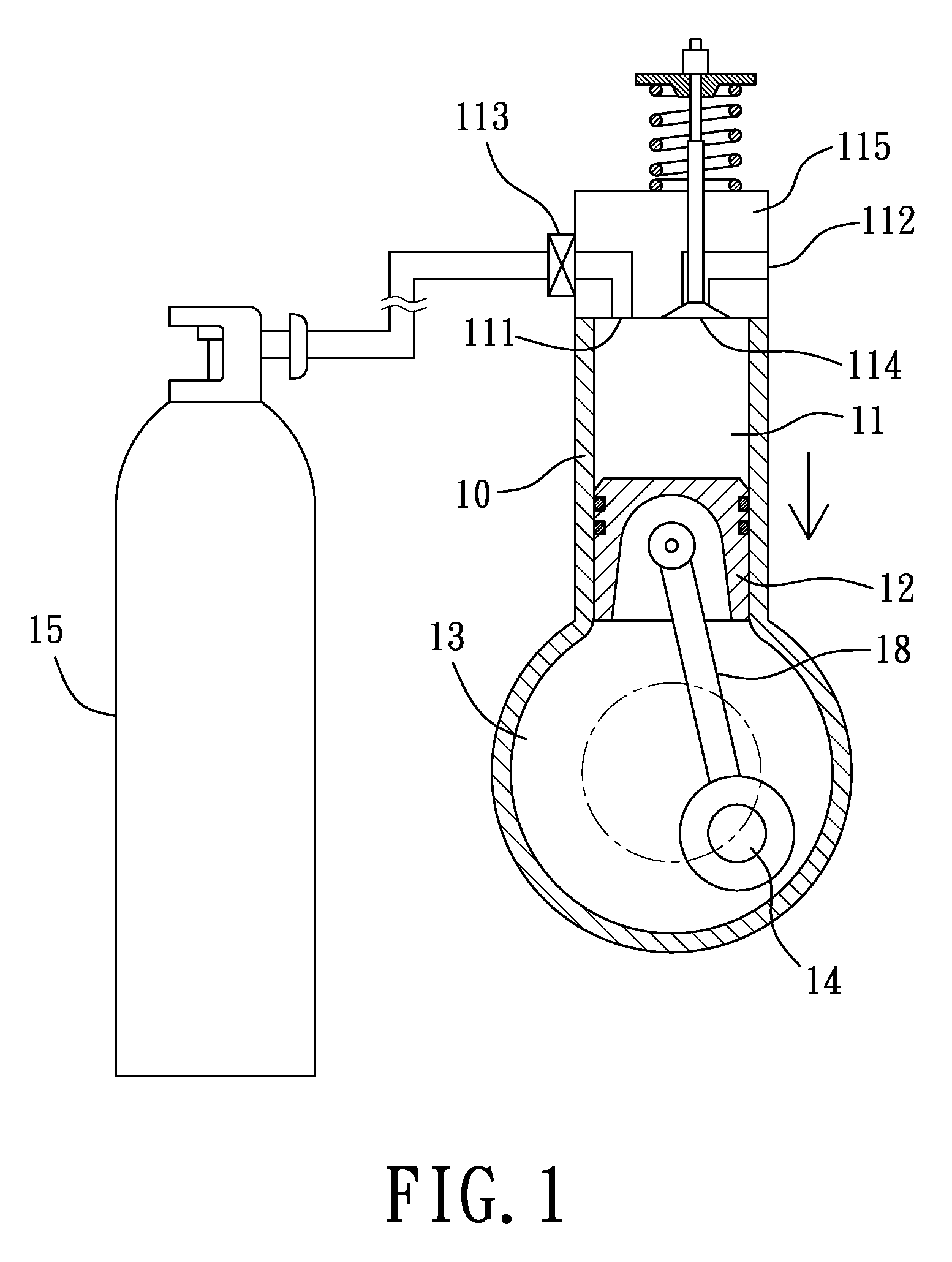
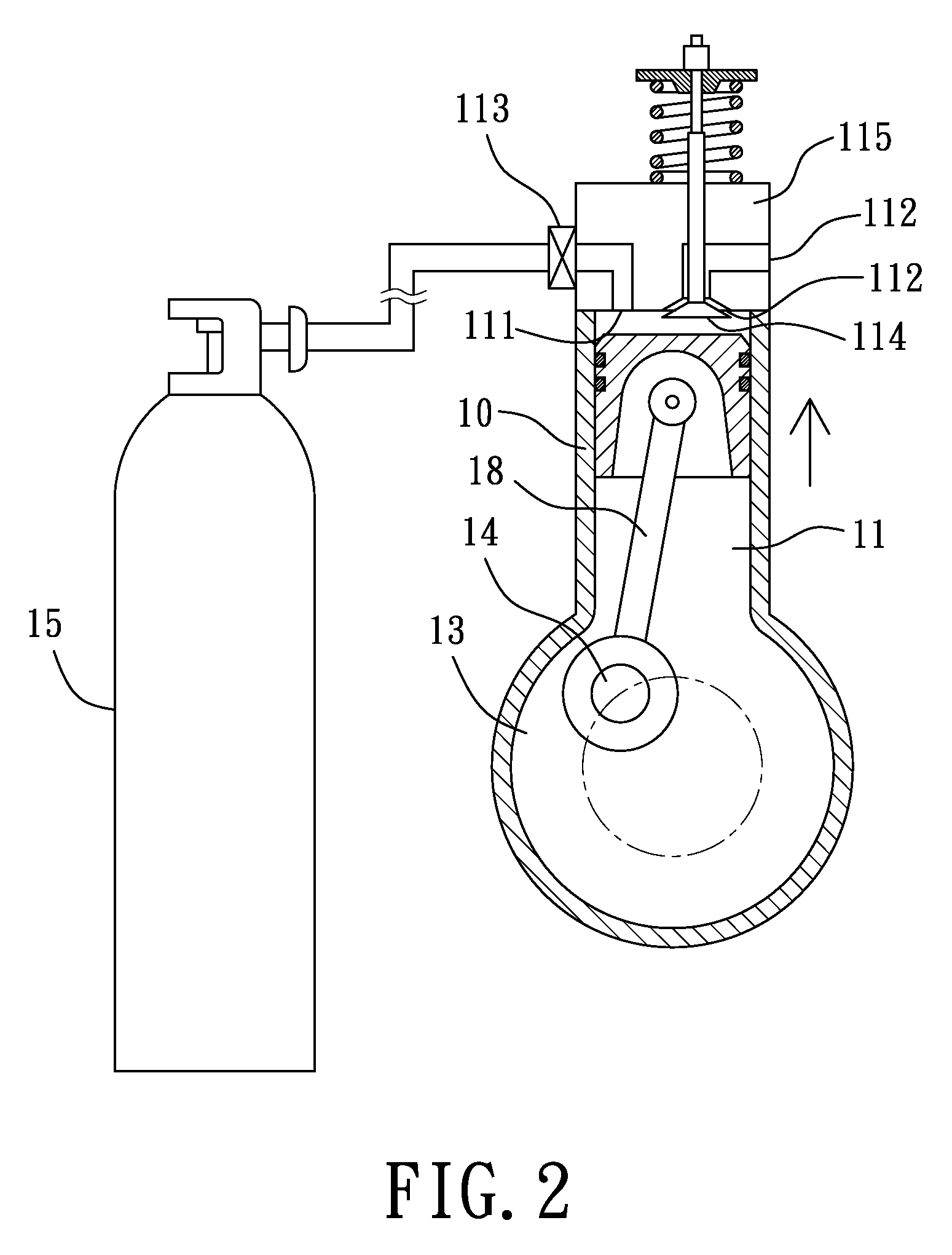
[0017]The design of the present invention is guiding high pressure gas into a cylinder having a piston and exhausting the high pressure gas out by controlling an admission valve and an exhaust valve to push the piston upwards or downwards and drive a crank member rotating for producing power.

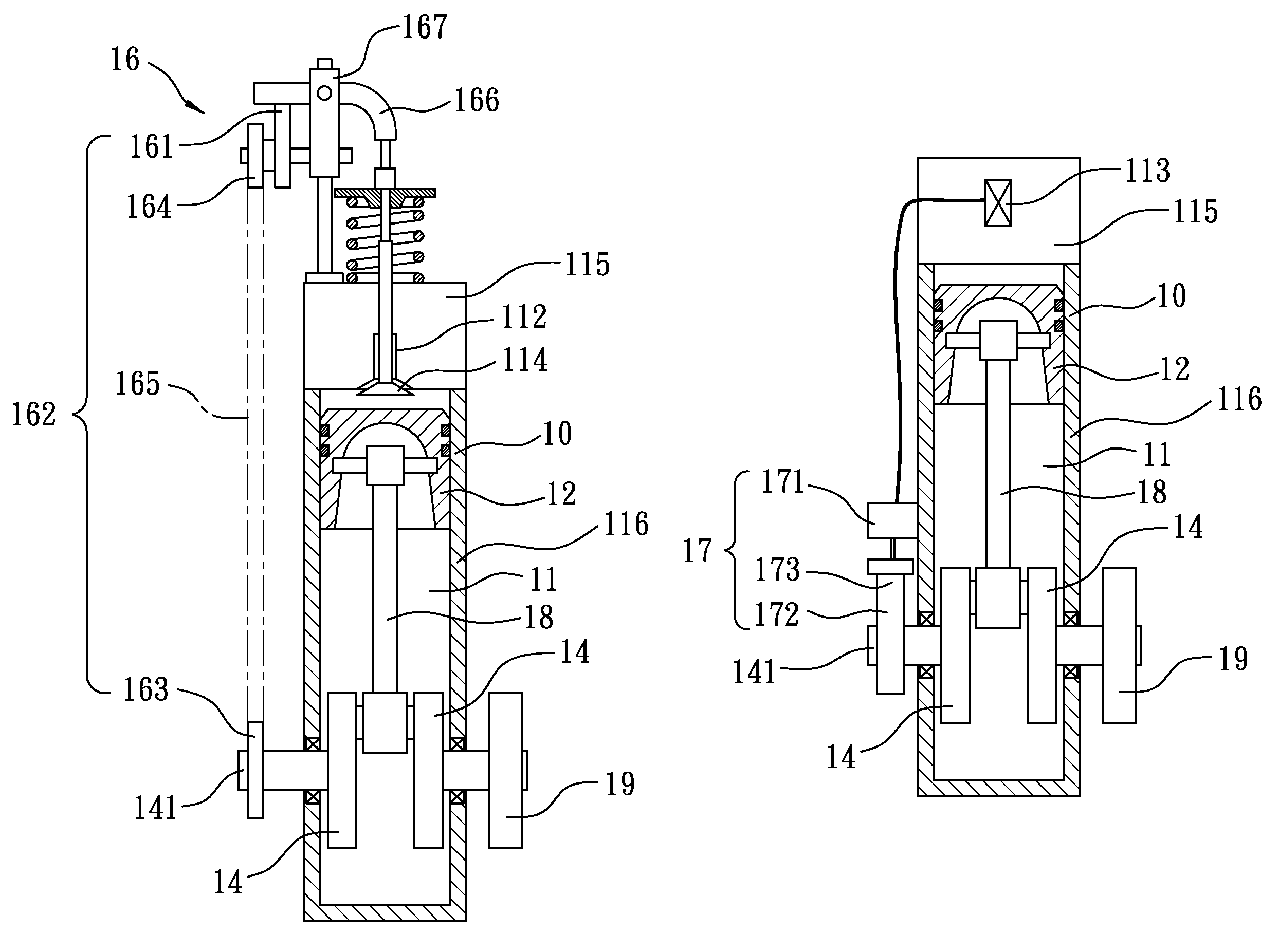
[0018]Referring to FIGS. 1-5, a power plant in accordance with a preferred embodiment of the present invention is shown. The power plant includes a cylinder body 10 and a supply device 15 for providing high pressure gas. The cylinder body 10 includes a cylinder 11, a piston 12, a crank chamber 13 and a crank member 14. The cylinder 11 has an admission passage 111 and an exhaust passage 112. An admission valve 113 is arranged in the admission passage 111, and an exhaust valve 114 is arranged in the exhaust passage 112. The piston 12 is arranged in the cylinder 11 and moveable ...


PUM


Abstract

A power plant produces power by using high pressure gas to push a piston. The power plant uses a supply device to provide the high pressure gas to a cylinder and controls an admission valve and an exhaust valve to admit and exhaust the high pressure gas for pushing the piston and rotating a crank member to produce power.

Description

FIELD OF THE INVENTION[0001]The present invention relates to power plants, and more particularly to a power plant by using high pressure gas to push a piston of a cylinder for producing power.DESCRIPTION OF THE RELATED ART[0002]Now, problems of energy sources focus on pollution produced by burning oil fuel, greenhouse effect, and exhausting in the future 30-50 years, etc. Current gas engines or engines generally use the oil fuel, such as oil or diesel oil, as the energy sources. Therefore, the oil fuel of the gas engines or engines burned will produce the pollution and produce the greenhouse effect. Furthermore, since the oil fuel is an unregenerate energy source, with the price of the oil fuel raises increasingly, global economy is impacted increasingly by the high price of the oil fuel. Therefore, an object of the present is designing a power plant producing no pollution.[0003]The inventors of the present invention work hardly to solve the above problems. With the long work, a pow...

Claims


Application Information

Patent Timeline
Patent Type & Authority Patents(United States)
IPC IPC(8): F01L25/08F01L15/14
CPCF01B17/025F01L1/12F01L1/18
Inventor NIEN, YU-HUN
Owner NIEN YU HUN
Learn More